
I n f ras t ru c t u re E n h a n c e m e n t an d
T r a f f i c M i t i g a t i o n P ro g r a m
Consultant Services Manual
Department of Transportation and Drainage
Submitted by
MOVEBR PROGRAM MANAGEMENT TEAM
Capacity Improvements – CSRS
Community Enhancements – Stantec
March 2021
CONSULTANT SERVICES MANUAL
iii MOVEBR CONSULTANT SERVICES MANUAL / MAR. 2021
Revision Control Log
Revision Date Issued Description of Changes Pages Affected

CONSULTANT SERVICES MANUAL
v MOVEBR CONSULTANT SERVICES MANUAL / MAR. 2021
Contents
Section Page
Revision Control Log ..................................................................................................... iii
Contents ......................................................................................................................... v
1 Introduction .............................................................................................................. 1
1.1. Purpose ........................................................................................................ 1
1.2. Project Team Interactions ........................................................................... 1
1.3. Design Standards and References ............................................................ 2
2 Quality Management .............................................................................................. 3
2.1. Quality Management Goals ...................................................................... 3
2.2. Quality Management Plan ......................................................................... 3
2.3. Review Processes ........................................................................................ 4
2.4. Computation Notebooks ........................................................................... 4
2.5. C-P Responsibility ........................................................................................ 5
3 Selection for Professional Services ......................................................................... 7
3.1. Consultant Selection Processes ................................................................. 7
3.1.1. Direct Solicitation and Appointment ....................................... 7
3.1.2. C-P Engineers and Surveyors Selection Board ......................... 7
3.2. MOVEBR Small Business Aspirations ............................................................ 8
4 Contract Negotiations ........................................................................................... 11
4.1. Pre-Proposal Meeting ............................................................................... 11
4.2. Scope and Fee Negotiations ................................................................... 11
4.3. Fee Proposal .............................................................................................. 12
4.3.1. Overhead Rates ....................................................................... 14
4.3.2. Profit Rate ................................................................................. 14
4.3.3. Markups .................................................................................... 14
4.3.4. Fee Proposal Template ............................................................ 15
4.4. Contract Execution ................................................................................... 15
5 Invoicing Requirements ........................................................................................ 17
5.1. General ...................................................................................................... 17
6 Standard Scope of Services.................................................................................. 18
6.1. General ...................................................................................................... 18
6.1.1. Health and Safety .................................................................... 18
6.2. Design Kick-off Meeting ............................................................................ 19
6.3. Planning, Scheduling, and Project Management .................................. 19
6.3.1. Project Correspondence ........................................................ 19
6.3.2. Work Planning and Coordination ........................................... 20
6.3.3. Project Schedule and Progress Reports ................................. 20
6.4. Project Meetings ....................................................................................... 22
6.4.1. Design Milestone Meetings ..................................................... 22
6.4.2. Design Coordination Meetings ............................................... 22
6.4.3. Design Progress Meetings ........................................................ 22

CONSULTANT SERVICES MANUAL
MOVEBR CONSULTANT SERVICES MANUAL / MAR. 2021 vi
6.4.4. Public Meetings ........................................................................ 23
6.4.5. Other Agency Meetings .......................................................... 23
6.5. Design Services and Milestones ............................................................... 23
6.5.1. Preliminary Engineering Services ............................................. 24
6.5.2. Final Plan Services .................................................................... 27
6.5.3. Other Services .......................................................................... 37
6.6. Additional Support Services ...................................................................... 42
6.6.1. Bid Phase Services .................................................................... 42
6.6.2. Construction Phase Services ................................................... 43
6.6.3. Record Drawings ...................................................................... 44
6.7. Services to be Performed by C-P and PMT ............................................. 44
7 Roadway Plan Preparation .................................................................................. 46
7.1. General ...................................................................................................... 46
7.1.1. Plan Size .................................................................................... 46
7.1.2. Plan Sheet Organization .......................................................... 46
7.2. Plan Set Content ....................................................................................... 46
7.3. Plan Modifications ..................................................................................... 48
Attachments
A Design Deliverable Checklists
B MOVEBR Quality Review Form
C MOVEBR Fee Proposal Template
& Example Computation of Hourly Rates
D MOVEBR Invoice Template
E Sample Project Schedule

CONSULTANT SERVICES MANUAL
1 MOVEBR CONSULTANT SERVICES MANUAL / MAR. 2021
1 Introduction
1.1. Purpose
This document outlines the standard processes for selection and contracting of professional
services, design process, project delivery, project team interactions. It helps define general
expectations for the City of Baton Rouge and Parish of East Baton Rouge (C-P) Department
of Transportation and Drainage (DTD), the Program Management Team (PMT), the MOVEBR
Technical Committee (MTC), and design consultants (Consultants) procured by the C-P for
professional services for following and successfully executing the overall design process for
all MOVEBR Program projects.
Information, requirements, check lists, and procedures regarding preparation of various
design milestone deliverables and final contract documents are presented herein. This
document provides guidance for a consistent yet flexible approach to the design process
and outlines the required design standards, including quality control measures for
deliverables. These guidelines will provide a common process for the MOVEBR Program
Project Manager (P-PM) and Consultants to follow regarding design procedures.
1.2. Project Team Interactions
The C-P has contracted a PMT to assist the DTD in managing and delivering MOVEBR
Projects and act as owner representative and advocate for the overall MOVEBR Program.
As such, the PMT will be the liaison between the Consultant team, most jurisdictional
agencies, third party vendors, the public, contractors, and the C-P/DTD. The PMT will be the
DTD representative and point of contact for the Consultant for most project design aspects
such as:
Contract Administration
i Negotiations
ii Scope determination & proposal evaluations
iii Pay request reviews
iv Project budget monitoring
Monitoring Design Progress

CONSULTANT SERVICES MANUAL
MOVEBR CONSULTANT SERVICES MANUAL / MAR. 2021 2
i Project schedule
ii Milestone submittal reviews
iii Stage gate approvals
Technical Assistance
Project Decision Support
Risk Management/Issue Escalation and Mitigation
Refer to Section 6.3.1 for further description of team interaction requirements.
1.3. Design Standards and References
Designs prepared as part of the MOVEBR Program shall conform to the MOVEBR Design
Guidelines, and the latest adopted version of all applicable local, state, and federal
regulations. Applicable codes and standards and their editions shall be verified at the time
of final design work. Design deviations may be incorporated into a project in accordance
with Section 1.3 of the MOVEBR Design Guidelines and subject to MTC approval.
Projects that are on state routes and not planned for transfer to the C-P, and for any
MOVEBR project that is currently a C-P route but planned for transfer to the LADOTD will
generally follow LADOTD Standards and Minimum Design Guidelines. The Consultant will be
required to follow the LADOTD design waiver/exception process for design deviations
needed on these routes. Approved waivers and exceptions will be incorporated into the
Project City-State Agreement and these design modifications shall be coordinated with the
Consultant.
CONSULTANT SERVICES MANUAL
3 MOVEBR CONSULTANT SERVICES MANUAL / MAR. 2021
2 Quality Management
2.1. Quality Management Goals
The following items represent the minimum quality management goals for the
MOVEBR Program:
Projects that are well-coordinated with one another.
Cost-effective design and construction. Cost-effective, sustainable, and
resilient operable and maintainable projects that meet the needs of the public
users.
Contract compliance.
Performance according to project schedule.
Application of sound engineering in plans and specifications.
Use of consistent processes and procedures.
Public disruption minimized during design and construction. Pro-active
communication and notification to public when changes or planned
disruption will occur.
Documented information in accordance with Program processes and
procedures.
Complete dissemination of information to all project team members.
2.2. Quality Management Plan
A project-specific Quality Management Plan (QMP) shall be submitted with the
Consultant’s Work Plan, including team assignments and the Consultant’s standard
quality management procedures. The Consultant shall appoint a Quality Manager for
the project. The Consultant’s Quality Manager shall:
Be available to the project engineer(s) and project manager for consultations,
and discussions as necessary.

CONSULTANT SERVICES MANUAL
MOVEBR CONSULTANT SERVICES MANUAL / MAR. 2021 4
Provide technical direction to the project team as necessary.
Review documents prior to submittal to the P-PM and sign the Design
Deliverable Checklists (see Attachment A) affirming that the quality review has
occurred, the documents meet the Consultant’s quality standards, and all
required components of the appropriate delivery milestone are included.
2.3. Review Processes
Key design submittals shall be reviewed in accordance with the Consultant’s QMP
prior to submission to the P-PM. Quality reviews will occur at each design milestone.
The Consultant shall:
Submit a letter of transmittal with the design deliverable, stating that the quality
review of the submittal has occurred, and the documents meet the submittal
requirements.
Design Deliverables Checklists, where applicable, will be signed by the
Consultant’s PM and the Consultant’s Quality Manager, and submitted with
the design milestone deliverables.
Design submittals must be uploaded to the MOVEBR Program SharePoint site
under the Consultant’s relative project folder. Consultant shall notify P-PM of
uploaded submittal via email and transmittal letter.
Review and understand PMT and C-P comments, which will be presented on
a standard Quality Review Form (QRF) (see Attachment B).
Respond to comments on the standard QRF.
Resolve differences between the author of the document and the reviewer.
Document the decisions made and/or direction given by the P-PM on the
project.
Coordinate with the P-PM for MTC Stage Gate reviews (as applicable) and
provide supporting documents as necessary.
2.4. Computation Notebooks
Calculations shall be prepared, checked, and reviewed. Calculations shall be made
available to the P-PM for informational purposes. Calculations required shall be, but
not necessarily limited to, the following:

CONSULTANT SERVICES MANUAL
5 MOVEBR CONSULTANT SERVICES MANUAL / MAR. 2021
Earthwork
Geometry checks
Roadside safety items such as guardrail lengths
Drainage
Fill mitigation (as applicable)
Green Infrastructure element calcs
Graphical Grade profiles
Bridge calcs
Other structural item calcs
Roadway Lighting calcs
Traffic movement AutoTurn analysis
Project notebooks shall be kept by the Consultant’s project manager and discipline
leads. Project notebooks shall contain engineering computations, engineering
assumptions and directions, pertinent correspondence, and completed checklists
with review comments. Although intermediate milestone submittals may require
computations, assumptions, correspondence, etc., all of these shall be recompiled
into one bound Computation Notebook and resubmitted at 100% Final Plan
deliverable. These project notebooks are part of the project documents and shall be
archived by the P-PM at the end of the project.
2.5. C-P Responsibility
The C-P, through its representative PMT, will provide contract administration,
management services, and technical reviews of all work associated with the
development and preparation of Contract Documents. The C-P technical reviews
are for high-level conformance and are not meant to be comprehensive reviews. The
Consultant shall be fully responsible for all work performed and work products
developed under their relative scope of services.
The C-P may augment the work by soliciting certain services under separate
agreements with other firms. The C-P will request that the Consultant coordinate with
the PMT and those firms to provide for a complete and successful project design

CONSULTANT SERVICES MANUAL
MOVEBR CONSULTANT SERVICES MANUAL / MAR. 2021 6
package. These services will be determined at the Pre-Proposal Meeting and may be
added as necessary after NTP on an as-needed basis.

CONSULTANT SERVICES MANUAL
7 MOVEBR CONSULTANT SERVICES MANUAL / MAR. 2021
3 Selection for Professional Services
3.1. Consultant Selection Processes
A P-PM will be assigned by the PMT to each design project. The P-PM will develop the
high-level design scope of work and estimated design cost for use in the selection of
professional design and support services. Based on the type of project and estimated
design fee, the C-P will select a Consultant through one of two processes, DTD direct
solicitation and appointment or public solicitation and selection by the C-P Engineer’s
and Surveyor’s Selection Board.
3.1.1. Direct Solicitation and Appointment
For projects or tasks with anticipated design fees less than $150,000, a Design
Consultant may be directly solicited and selected for each project or task through
the direct appointment of the Director of Transportation and Drainage.
Consulting firms interested in doing work for the C-P are encouraged to submit their
interest and company information through the MOVEBR website
(https://movebr.brla.gov/page/professional-services). Company names and
information will be collected and maintained in a database listing for future project
selections. The PMT will negotiate the contract terms with the Consultant on behalf
of the C-P.
3.1.2. C-P Engineers and Surveyors Selection Board
For larger projects with anticipated design fees $150,000 and greater, a Design
Consultant (Engineer) will be publicly solicited and selected for each project through
the C-P Engineer’s and Surveyor’s Selection Board in accordance with Ordinance
8931. The P-PM will negotiate the contract terms with the Engineer on behalf of the
C-P.
The C-P will publicly advertise Request for Qualifications (RFQs) for MOVEBR projects
through the official journal of the Parish (The Advocate newspaper) and through the
Baton Rouge Projects website (https://rfqmanager.brprojects.com). Interested
engineering firms shall register through the web-based RFQ manager. The RFQ
package will include a preliminary scope of work to assist the Consultants in selecting
the appropriate teaming arrangement, sub-consultants and specialty sub-
consultants.
CONSULTANT SERVICES MANUAL
MOVEBR CONSULTANT SERVICES MANUAL / MAR. 2021 8
3.2. MOVEBR Small Business Aspirations
The C-P is committed to ensuring that small, disadvantaged, minority, veteran and
women-owned businesses are not precluded from competing for, proposing on, or
bidding on advertised professional service and construction related opportunities
planned by the MOVEBR Program. To support this commitment, the PMT provides for
Small Business Outreach (SBO) to create, implement and monitor a plan to increase
and maximize contracting and procurement opportunities for small businesses
enterprises, including Certified and Noncertified DBE firms, throughout the entire
MOVEBR program. This small business outreach effort is primarily targeted at the local
level, which are those businesses in East Baton Rouge Parish who aspire to do business
or continue doing business with the C-P.
While no mandatory or specific participation goal has been formally adopted for C-
P contracts, Consultants are strongly encouraged to utilize local small business
enterprises, including Certified and Noncertified DBE firms participation in all C-P
contracts to the extent possible.
To assist larger design firms in identifying small, disadvantaged, minority, veteran and
women-owned businesses as potential teaming partners, the PMT has created a
database of firms and their corresponding services offered. This database is available
on the MOVEBR website at https://movebr.brla.gov/page/direct-appointment-
candidates. These firms have self-certified under one or more of the categories as
defined below:
Minority Business Enterprise (MBE) – means a business which is at least fifty-one
percent (51%) owned by African Americans, American Indians, Asians, Filipinos,
and/or Latinos and whose management and daily operation is controlled by
one or more members of the identified ethnic groups.
Women Business Enterprise (WBE) – means a business which is at least fifty-one
percent (51%) owned by one or more women and whose management and
daily operation is controlled by the qualifying parties.
Veteran Owned Business (VOB) – means a business which is at least fifty-one
percent (51%) owned by one or more Veterans and whose management and
daily operation is controlled by the qualifying parties.
Local – means a business that has a permanent address within the Parish of
East Baton Rouge for a period of at least 12 months prior to the date of the
contract. Temporary construction offices or Post office boxes do not constitute
a business location under this definition.

CONSULTANT SERVICES MANUAL
9 MOVEBR CONSULTANT SERVICES MANUAL / MAR. 2021
State - means a business that has a permanent address within the State of
Louisiana for a period of at least 12 months prior to the date of the contract.
Temporary construction offices or Post office boxes do not constitute a business
location under this definition.
In addition to the database MOVEBR has launched a video library as a resource to
meet small businesses for teaming opportunities. Several small, disadvantaged,
minority, veteran and women-owned companies have recorded brief introductory
messages introducing and describing their businesses. This small business video library
is available at https://movebr.brla.gov/page/small-business-video-library
CONSULTANT SERVICES MANUAL
11 MOVEBR CONSULTANT SERVICES MANUAL / MAR. 2021
4 Contract Negotiations
4.1. Pre-Proposal Meeting
A pre-proposal meeting will be held between the PMT and the Consultant. DTD
representatives will be invited to attend at their discretion. At the pre-proposal meeting,
the Consultant will be provided a Project Concept Report, Sample Contract for
Engineering Services, and Standard Scope of Engineering Services. As part of the pre-
proposal meeting, a site visit may also be made to familiarize the project team with the
project site and to review the project scope.
Primary information included in the Concept Report will include:
Detailed project description, layout sketches, limits, and boundaries
Design criteria and requirements
Special design, coordination or construction requirements
Type of construction contract preferred (e.g., lump sum, unit price)
4.2. Scope and Fee Negotiations
To evaluate the reasonableness of the proposed fee and facilitate progress payments, it
is required that proposals be written in such a manner that provide adequate cost
breakdown details. The Consultant shall provide a drawing/task list at each design phase
along with the associated man-hours. The Consultant shall at this time also prepare a
high-level schedule for each design phase to aid in determination of contract time and
ensure consistency with Program schedules. The fee shall be submitted in the MOVEBR
Fee Proposal Template to be provided by the P-PM at the pre-proposal meeting. Any
changes (additions, removal, or variations) in the Standard Scope of Services, as
described in Section 6, resulting from specific project requirements and/or the fee
negotiations shall be clearly documented in the Project Specific Scope and Fee
Proposal.
Included in the Project Specific Scope, the Consultant shall prepare a detailed list of
assumptions that were used to develop the fee proposal.
Once the Consultant has submitted the fee proposal, the C-P and the PMT will review the
proposal to ascertain the following:
CONSULTANT SERVICES MANUAL
MOVEBR CONSULTANT SERVICES MANUAL / MAR. 2021 12
Compliance with the requested scope of work, completeness, and
understanding.
Clarification of ambiguity in the draft proposal especially related to deliverables
at each phase of the work.
Consistency with the proposed schedule or milestones.
The fee proposal is fair and within the normal range for work of this type and within
the funds set aside in the Program Budget.
Contract negotiations will proceed as follows:
Following review of the initial fee proposal, a negotiation meeting between the
Consultant and the P-PM will be held.
The Consultant will re-submit their fee proposal based on comments received.
The P-PM and C-P will review the revised fee proposal, and a second negotiation
meeting will be held (if necessary).
The Consultant will submit a final fee proposal.
The P-PM will send the final fee proposal to the C-P with or without endorsement.
If satisfactory negotiations do not result, the top-rated consulting firm shall be notified in
writing that a contract cannot be reached, and the C-P/PMT will proceed to negotiate
with the second rated consulting firm as identified by the original selection process. If an
acceptable contract cannot be reached with the second consulting firm, they too, will
be notified of such in writing and the C-P/PMT will proceed to negotiate with the third
consulting firm. If an acceptable contract cannot be reached with any of the top three
firms, the project will be re-evaluated and re-advertised. In all cases, once contract
negotiations have been terminated with a firm and begun with another, they will not be
reopened with the former firm or firms. The negotiated fee and contract agreement are
subject to Metropolitan (Metro) Council final review and authorization of the Mayor-
President to execute the contract for engineering services for this project.
4.3. Fee Proposal
Professional service contracts will generally be structured as lump sum fees. These
contracts depend upon having a detailed scope of services and a clearly defined final
product that has been broken down into identified phases of work. Exceptions to this
may be associated with tasks such as bidding support services and

CONSULTANT SERVICES MANUAL
13 MOVEBR CONSULTANT SERVICES MANUAL / MAR. 2021
construction/inspection support services which will be hourly time and material fees. The
Consultant’s compensation would be based upon an estimate of:
Total work hours per job classification/salary class
Sum of all work hours per job classification/salary class
Audited overhead business expense factor
Applied Profit factor
Plus, the addition of the sum of estimated direct expenses
In preparation of the proposal, the Consultant should note the following instructions:
a. The proposal will contain a recap of the proposed fees by phase or task as well
as a proposed time limit for each phase or task.
b. Caution should be exercised to make certain that work does not overlap
between line items and/or between prime and subconsultant tasks.
c. Proposed personnel/classification and associated pay rates must be
commensurate with work/tasks to be performed. For example, if a principal
anticipates charging time to the project at a principal’s rate, this item must be
included as “Principal’s time” and be extended with the other salaries. If the
principal works at any other classification, these man hours will be included
with that classification.
d. All lump sum proposals shall be supported by schedules which show in detail
how the hourly rates are derived (See example in Attachment C). Consultant
shall retain this schedule in case in case of audit by the C-P or requested to
submit with proposal. If it is not known which employees will be utilized in the
project, then all employees within a particular classification should be given
equal weight in calculating the rate.
e. In preparation of the proposal, Consultant is cautioned not to estimate the cost
of the project and use a curve to determine a fee and after which adjust
manhours and profit to fit.
f. The Consultant, by submitting a proposal, acknowledges he or she has read
the entire sample contract and is familiar with the requirements.

CONSULTANT SERVICES MANUAL
MOVEBR CONSULTANT SERVICES MANUAL / MAR. 2021 14
4.3.1. Overhead Rates
The DTD will generally accept all reasonable firm overhead rates if the Consultant
provides justification in the form of a LADOTD audited or Certified Public Accountant
audited overhead rate determination letter. The overhead rate will be applied to the
labor costs. The Consultant must submit overhead audit letters for themselves and all
subconsultants included in the fee calculations.
4.3.2. Profit Rate
The maximum profit percentage allowed by DTD is 15% for general engineering/related
services and 12% for construction support/inspection and other field services. Profit may
be adjusted based on the overhead factor. The overhead factor used in the lump sum
fee profit computation is based upon the comparison of the firm’s justified overhead rate
to the statewide average overhead. The overhead factor is C
2
, where C is the ratio of
statewide average overhead to contract overhead, up to a maximum value of 1.00.
This policy is similar to the LADOTD’s profit adjustment factor, except it is only applied
when a firm’s overhead rate is higher than the current LADOTD statewide average
overhead rate by a predetermined amount. At the time of this publication (2020), the
statewide average general overhead rate is 156.16% and field overhead rate is 111.75%.
DTD’s determined profit adjustment trigger value is:
General overhead rate of 176% or greater
Field overhead rate of 132% or greater
This value will be reviewed and updated on an annual basis when the statewide average
is published by LADOTD.
Example:
Prime’s OH factor is 194.75%. This is greater than 176.00%, therefore the profit
adjustment shall be implemented.
The adjustment factor, C
2
, is (156.16/194.75)
2
= 0.6429. Therefore, the profit rate
should be adjusted to 15% x C
2
= 9.64%.
4.3.3. Markups
DTD allows the Consultant a 10% markup on all subconsultants’ fees to cover any risk,
coordination, management, and administrative costs related to the subconsultants’
work. No markup is allowed on direct expenses.
CONSULTANT SERVICES MANUAL
15 MOVEBR CONSULTANT SERVICES MANUAL / MAR. 2021
4.3.4. Fee Proposal Template
A standardized fee template was developed to aid the Consultant in preparing the fee
estimate, provide a consistent format for the PMT to review, and automation of certain
redundant information. The template is a MS Excel
®
spreadsheet that includes individual
tabs for the varying tasks involved in the design effort. These tasks follow along with both
the MOVEBR Design Guidelines and this Consultant Services Manual. These tasks will roll
up to three main phases of work:
Preliminary Engineering Services
Final Plan Services
Other Services
The standardized invoice template, described in Chapter 5, will utilize the same tasks titles
for invoicing purposes. The tasks provided in the fee template are not a substitute for a
well-documented scope document to accompany the fee proposal. All links and
formulas contained in the template spreadsheet are included for convenience only, the
Consultant is responsible to ensure all information is accurate prior to submittal to the P-
PM. The Consultant shall strictly follow the instructions in the provided fee template and
shall not modify any formulas without coordination and approval of the P-PM.
4.4. Contract Execution
There are two main procedures for processing design service contracts based on the size
of the fee. Contracts for $50,000 or greater (cumulatively) must receive authorization
from the Metropolitan Council (Metro Council) for the Mayor-President to enter into the
agreement, and the Mayor must sign if granted authorization from the Metro Council.
This process is somewhat time consuming since it must be placed on a Metro Council
agenda to be introduced at one meeting and then be heard for public comment at a
second meeting, generally two weeks later.
Contracts less than $50,000 do not require authorization from the Metro Council and can
be signed by the Purchasing Director rather than the Mayor-President.
Once a scope and fee have been agreed to, a services agreement will be drafted and
forwarded to the consulting firm for review of terms and partial execution. Upon
agreement to the terms, the Consultant shall sign the agreement and return partially
executed agreement to the P-PM along with:
a signed and notarized Affidavit,
corporate authorization granting representative authorization to sign on behalf of
the corporation (corporate resolution), and

CONSULTANT SERVICES MANUAL
MOVEBR CONSULTANT SERVICES MANUAL / MAR. 2021 16
certificates of insurance (see example contract for insurance requirements).
If the Consultant has not previously registered with the C-P Purchasing Department’s
Vendor Self Service (VSS) portal, they should do so prior to submitting the partially
executed contract. More information regarding VSS can be found at the following
website: https://www.brla.gov/437/Vendor-Information.
Upon receiving a fully executed contract from the C-P, the P-PM will contact the
Consultant to discuss and agree on a date to issue the formal Notice to Proceed (NTP).
Once the date is agreed to a NTP will be drafted and forwarded along with a copy of
the fully executed contract to the Consultant. The P-PM will then follow up with the
Consultant on scheduling a date for the Design Kickoff meeting.

CONSULTANT SERVICES MANUAL
17 MOVEBR CONSULTANT SERVICES MANUAL / MAR. 2021
5 Invoicing Requirements
5.1. General
The Consultant shall prepare and submit monthly invoices for services completed in
accordance with the executed contract. A monthly invoice is required for each project
under an active contract even if the amount is $0.00. A standardized invoice template
was developed to aid the Consultant in preparing the monthly invoices. This template
will be provided to the Consultant by the P-PM for each project. The invoice will be
accompanied by backup documentation described below.
As explained in Section 3.2, to assist the C-P in its efforts to track the small minority and
local business participation on its professional services contracts, the Consultant will
include a “Contract Activity Report” with each monthly invoice. This report is included in
the invoice template. Engineer shall complete and submit a Contract Activity Report as
an attachment to each monthly invoice.
A progress report and updated schedule shall be submitted to the P-PM along with each
monthly invoice. The progress report shall be in a format and arrangement approved by
the P-PM; it should show actual progress in comparison to the original project schedule
and summarize major tasks completed since the last report. A progress report template
is included in the invoice template file. Any invoice that does not include the required
backup documentation will be rejected for resubmittal. Consultant shall not invoice
more than 90% of a specific milestone until the corresponding deliverable has been
reviewed by the PMT, all review comments have been discussed, resolved, documented,
and approval to begin the next milestone phase has been authorized.
Each invoice must reconcile with the previous invoice. Therefore, subsequent invoices
will not be processed until the previous invoice is deemed correct. The invoice template
file should be kept on the MOVEBR SharePoint project folder, checked out to modify
monthly, and checked back in once complete. The Cover Letter, Invoice, Contract
Reporting, and Progress Report tabs should be printed in PDF format and posted to the
SharePoint site with notification to your P-PM for your monthly invoice. To assure prompt
review and payment Consultants should not send invoices (or even a copy) directly to
the DTD or Department of Finance. This will only cause confusion and delay payment.
Payments to the Consultant on undisputed amounts for services invoiced by the
Consultant shall be paid in accordance with the contract.
For projects along state routes, the invoice template should match the standard LADOTD
invoice template and formatting. The MOVEBR Contract Activity Report information will
be added to the LADOTD standard invoice along with the progress report and updated
schedule.
CONSULTANT SERVICES MANUAL
MOVEBR CONSULTANT SERVICES MANUAL / MAR. 2021 18
6 Standard Scope of Services
6.1. General
The Consultant shall provide engineering services for the C-P, as described by the specific
scope of services required for each project. Projects along state routes will have to follow
the standard scope of services for LADOTD requirements and submittals. The following
section provides a general scope of services that will be required for most MOVEBR
Program projects.
The Consultant shall perform all design activities under the supervision of the PMT in
accordance with the following standards and criteria:
MOVEBR Consultant Services Manual
MOVEBR Design Guidelines
MOVEBR CAD Templates
MOVEBER Right of Way Map Checklist
MOVEBR Design Deliverables Checklists (Note that the checklists contain the
minimum requirements for each submittal and the Consultant shall submit
information in addition to the items included in the checklists as requested by the
P-PM)
C-P Standard Specifications and Standard Details (SS&D)
The PMT shall furnish the Consultant electronic copies of the title sheet template, plan
sheet border template, and standard details for consistency in plan preparation.
Ownership of the drawing templates and details is transferred to the Consultant upon
receipt. Professional responsibility as Engineer of Record (EOR) for the Contract
Documents belongs to those individuals who apply their seals to the Contract
Documents. The PMT may issue additional details during the project. The Consultant shall
be responsible for the preparation of project-specific details and specifications and
verifying the appropriateness of the standard specifications and details provided by the
PMT or C-P.
6.1.1. Health and Safety
The Consultant is solely responsible for the health and safety of its employees and
subconsultants.

CONSULTANT SERVICES MANUAL
19 MOVEBR CONSULTANT SERVICES MANUAL / MAR. 2021
6.2. Design Kick-off Meeting
The Consultant shall attend a kick-off meeting scheduled by the P-PM to identify key
personnel, define responsibilities and discuss procedures, standards, schedules, and
program guidelines to be followed for:
Development of the preliminary engineering Design Study
Review of existing project site and/or community context specific issues
Review of project-specific technical issues
Review of project-specific land acquisition, permitting and utility conflict issues,
and permit application requirements
Discussion of alternative solutions to be evaluated
The Consultant shall prepare the agenda, a draft memorandum of decisions and action
items resulting from the meeting and distribute to all meeting participants within one
week after the meeting. Comments from meeting participants will be addressed in a final
record memorandum and distributed to all meeting participants within two weeks after
the draft memorandum submittal.
6.3. Planning, Scheduling, and Project Management
The Consultant shall provide project management and coordination activities during all
phases of the Project. Specific requirements are as detailed below.
6.3.1. Project Correspondence
The Consultant shall reference the C-P project title and C-P project number on all
correspondence and submittals. All project correspondence shall be addressed and
transmitted to the P-PM for proper tracking and distribution to the C-P.
The Consultant shall communicate with the P-PM through a single point of contact
identified as the Consultant’s Project Manager (PM). The P-PM will in turn communicate
with the C-P and communications to the Consultant shall be addressed through the PM.
Prior to the start of each project the name and address of the point of contact for each
party for that project shall be established.
CONSULTANT SERVICES MANUAL
MOVEBR CONSULTANT SERVICES MANUAL / MAR. 2021 20
6.3.2. Work Planning and Coordination
The Consultant shall provide the following project management activities:
Establish a Project Work Plan for the preliminary engineering Design Study, final
design, and bidding of the project.
i Submit the Work Plan to the P-PM for review within 30 days of the Notice to
Proceed (NTP) and prior to submission of the Consultant’s first invoice. No
payments will be made to the Consultant until the Work Plan is reviewed
and accepted by the P-PM.
ii The project Work Plan shall include project organization/staffing chart,
project schedule, Minority/Disadvantaged business participation, QMP,
health and safety considerations, change management, and other project
management requirements. The Project Work Plan shall include the
proposed project schedule which shall show the proposed dates for design
milestones as outlined in the Contract. The project Work Plan shall be kept
up-to-date, and changes to the Work Plan shall be submitted to P-PM with
the monthly invoice.
Plan and monitor project fee budgets and delivery schedules.
Monitor quality and conformance to the MOVEBR Design Guidelines.
Coordinate with third-party consulting firms under contract with the C-P to perform
services related to and in support of the Consultant’s project.
Coordinate the design with other ongoing infrastructure work including State
project, other MOVEBR Program projects, and other C-P projects such as road
rehabilitation or wastewater projects.
Maintain project documents.
Notify the P-PM immediately if the Consultant believes that action required by
directions, clarifications, or other communication from the DTD and/or PMT will
cause the Consultant to deviate from the Scope of Engineering Services, fees, or
schedule agreed to herein.
6.3.3. Project Schedule and Progress Reports
The Consultant shall prepare and submit a detailed project schedule and submit it to the
P-PM for comment and approval in a mutually agreed upon format (see example in
Appendix E). The schedule shall show dates for:
CONSULTANT SERVICES MANUAL
21 MOVEBR CONSULTANT SERVICES MANUAL / MAR. 2021
NTP for phase of work
Design meetings including milestone, coordination and progress meetings
Design milestones
PMT/DTD review and MTC Stage Gate approvals
Permit application submittals and approvals
Bid advertisement (Construction letting)
The project schedule shall be kept up-to-date, and changes shall be submitted to the P-
PM with the monthly progress report and invoice.
Progress reports shall include:
The current status and percent complete of each activity noted in the Contract
including work by subconsultants
Activities and deliverables completed in the current reporting month
Activities and deliverables planned for next month
Any anticipated variances from the project schedule
Any ROW related issues/concerns
Any utility related issues/concerns
Any agency coordination needs or issues of concern
Any other risks/issues of concern
Progress reports will be used by the P-PM to determine percent complete of work by the
Consultant as a basis for payment. Therefore, they shall include adequate detail for the
P-PM to confirm that the invoice amount is commensurate with the work completed. Any
variances from the project schedule identified in the progress reports shall be addressed
in writing by the Consultant, noting a recovery schedule plan, additional staffing needs,
or proposed schedule modifications.

CONSULTANT SERVICES MANUAL
MOVEBR CONSULTANT SERVICES MANUAL / MAR. 2021 22
6.4. Project Meetings
Project meeting type and frequency with the DTD and PMT shall be as outlined below.
The Consultant will be responsible for preparing and delivering a record memorandum
of decisions and action items to the meeting attendees within three days after each
progress meeting. Comments from meeting participants will be addressed in a final
record memorandum and distributed to all meeting participants within one week after
the draft memorandum submittal.
The Consultant shall notify the P-PM immediately if the Consultant believes that action
required by directions, clarifications or other communications from the DTD and/or PMT
will cause the Consultant to deviate from the Scope of Engineering Services, fees, or
schedule agreed to herein.
6.4.1. Design Milestone Meetings
Following a typical two-week review period by the DTD and PMT of the Design Study, 30,
50 (if applicable), 60, and 90 percent deliverables, design milestone meetings may be
held, if necessary, between the Consultant, DTD, and PMT to discuss the design packages
and receive and resolve comments. If a design milestone meeting is necessary, it will
take the place of the next scheduled Design Progress Meeting (see below). Within one
week after a milestone meeting, the Consultant will prepare and deliver a record
memorandum of decisions and action items to the meeting attendees.
6.4.2. Design Coordination Meetings
Consultant shall participate in coordination meetings as necessary with the DTD, PMT,
and possibly other jurisdictional agencies to discuss and coordinate technical elements
of the design and scope of services, design criteria, design alternatives, site issues and
other relevant topics.
6.4.3. Design Progress Meetings
Review of the project will also occur with the DTD and PMT during the course of design in
bi-weekly progress meetings. The Consultant will prepare an agenda and submit it to the
P-PM prior to each meeting. The following items, at a minimum, shall be discussed at each
bi-weekly meeting:
Anticipated variances from the project schedule, reasons for variance and
recovery schedule plan
Anticipated variance from the Scope of Engineering Services and reasons for
variance
Status of land acquisition activities as performed by the PMT
CONSULTANT SERVICES MANUAL
23 MOVEBR CONSULTANT SERVICES MANUAL / MAR. 2021
Status of necessary permit applications and approvals
Status of coordination with utilities
Within one week after each meeting, the Consultant will prepare and deliver a record
memorandum of decisions and action items to the meeting attendees.
6.4.4. Public Meetings
The Consultant may be expected to attend public meeting(s), assist with meeting setup
and take down. If attending, the Consultant will attend the meetings with an appropriate
number of personnel to assist the C-P and PMT.
The Consultant will prepare the necessary materials for use in public meetings. Prepare
exhibits for the meeting, appropriate to the meeting format, and generally providing the
following information:
Project’s purpose, needs, goals, and any local urban planning
Project alternatives and major design features
ROW acquisition process
The established procedures for receiving written and oral statements
The Consultant may also be asked to prepare a summary of the public meeting that
includes all copies of all materials shown or provided at the public meeting. The summary
should also include a listing of all written comments made during or after the meeting
and responses to those written comments. In general, most projects will have two public
meetings; one meeting during the Design Study phase and the final meeting prior to
construction.
6.4.5. Other Agency Meetings
In addition to scheduled public meetings the Consultant may be required to participate
in meetings with local, state, federal governing authorities. The Consultant’s participation
may include, but not be limited to, presentations during the meeting, note taking, and
summarizing the meeting in a memo to the file.
6.5. Design Services and Milestones
The applicable design services and milestones are listed in the “Compensation and
Payment” section of the Contract, and the designation of fees associated with each
design milestone shall serve as the basis for invoicing by the Consultant. A description of

CONSULTANT SERVICES MANUAL
MOVEBR CONSULTANT SERVICES MANUAL / MAR. 2021 24
the activities and required deliverables associated with each design milestone is
included herein. All work is to be performed based on the specific Project Scope and as
directed by the DTD and PMT.
No design milestone phase is considered complete until all previous review comments
have been discussed, resolved, documented, and approval to begin the next milestone
phase has been authorized by the PMT or DTD. This does not necessarily mean comments
have to be incorporated into the deliverable and resubmitted prior to moving toward
next milestone, unless such comments are deemed by the PMT or DTD to affect
completeness of the milestone. In general comments are incorporated into the next
design milestone submittal.
6.5.1. Preliminary Engineering Services
6.5.1.1. Design Study
Under the Preliminary Engineering Phase, the Consultant shall prepare a Design Study.
The purpose of the Design Study is to provide a conceptual design, quantify the right-of-
way (ROW) requirements, and establish a preliminary construction cost estimate for the
project. For some projects (Corridor Enhancement Projects) the Design Study phase will
include development and evaluation of several design alternative concepts with input
from public meetings, C-P, and PMT. It also includes the results of environmental,
geotechnical, traffic studies and other considerations to determine the most feasible
project design.
In addition to the Design Study, the MOVEBR Project Design Report (PDR) as described in
the MOVEBR Design Guidelines will be prepared and finalized during the Preliminary
Engineering Phase. The PDR will document selection and approval of design criteria
values and design element implementation decisions for the project. As dictated in the
Design Guidelines, the Preliminary PDR will be prepared and submitted as an
intermediate (30%) submittal during the Preliminary Engineering Phase. The Final PDR will
be submitted with the final Design Study deliverable.
The Design Study shall be prepared in an 11” x 17” format and at a minimum include the
following parts:
Cover Sheet - A cover sheet that includes the project title, project number, date, design
speed, roadway context and functional classification, and layout map showing the
location and limits of the proposed project.
Narrative - A narrative section containing the following:
Project Description
Listing of the Existing Data
CONSULTANT SERVICES MANUAL
25 MOVEBR CONSULTANT SERVICES MANUAL / MAR. 2021
Summary of the Traffic Design Report
Summary of the Environmental Studies
Typical Section and Roadway Alignment Description
Preliminary Drainage Analysis (including potential stormwater mitigation
opportunities and fill mitigation requirements).
Pond Siting Analysis– If a stormwater detention pond is determined to be
appropriate, a Pond Siting Analysis shall be required as part of the Design Study
submittal. Consultant shall evaluate pond sites using a preliminary hydrologic
analysis.
Bridge Type, Size and Location
Bridge preliminary hydraulic study and scour analysis
Preliminary Opinion of Probable Construction Cost
Earthwork Model - The typical section template shall be applied to the existing digital
terrain model, based on LIDAR data, to determine the proposed roadway surface and
approximate limits of construction.
Figures and Exhibits -
Typical Section(s) – The proposed preliminary typical section(s) and a template
created for the earthwork model.
Project Layout – Layout sheet(s) showing the overall plan-profile sheet sequence
(mainline and crossroads).
Plan and Profile Sheets – Plan and profile sheets shall be provided on aerial
background at a scale of 1"=20' (unless otherwise approved) on 22”x 34” sheet
size. Drawings are to be prepared so they are readable at 50% reduction (11X17”
sheet size). The plan and profile sheets shall include the following information.
i Any existing topographic features that may have been surveyed under
preliminary limited scope up to this point
ii Name of roadway and intersecting roadways
iii Roadway and median dimensions

CONSULTANT SERVICES MANUAL
MOVEBR CONSULTANT SERVICES MANUAL / MAR. 2021 26
iv Median openings
v Transition locations and lengths
vi Horizontal alignment and curve data (including stationing)
vii Approximate limits of construction
viii Apparent Existing R/W and preliminary required R/W
ix Existing ground line (from LIDAR data)
x Profile grade line and vertical curve data
xi Design flood stage with design frequency
xii Proposed bridge limits
Existing Drainage Map – The existing drainage map shall include the drainage
boundaries, drainage area sizes, direction of flow, and the sizes of existing
drainage structures if available.
Green Infrastructure Planning Level Analysis (refer to Design Guidelines for
requirements)
Deliverables:
Electronic copy of the Preliminary PDR in pdf format submitted separately at
approximately 30% Design Study progress
Electronic copy of the Design Study in pdf format
Electronic copy of the Final PDR in pdf format
6.5.1.2. Preliminary Environmental Studies
Environmental review needs will be determined on a project by project basis but could
include the following as outlined in the MOVEBR Design Guidelines:
Wetland delineation and permitting
Phase I Environmental Site Assessment (ESA)

CONSULTANT SERVICES MANUAL
27 MOVEBR CONSULTANT SERVICES MANUAL / MAR. 2021
Required studies will be addressed in the Pre-proposal meeting. In most cases all projects
will require a draft Phase I ESA Report and wetland delineation report. The Phase I ESA
shall follow the procedures described in the MOVEBR Design Guidelines. These may be
acquired through third party contracted services and provided to the PMT and
Consultant by the C-P. Reports shall be submitted in PDF format.
The PMT will review the Draft Environmental Studies (as required) and provide comments
subject to resolution by the Consultant. Resolution of the comments shall be incorporated
in the Final Environmental Study or Report.
Should recognized environmental condition(s) be identified during the Phase I ESA, the
Consultant shall prepare and submit to the P-PM a Technical Memorandum and cost
proposal noting specifics of the identification of the recognized environmental
condition(s) and including recommendations that a Phase II ESA be performed.
6.5.1.3. Corridor Survey
Control surveys and topographic surveys shall comply with the MOVEBR Design
Guidelines, and DOTD’s Location and Survey Manual and shall include all topographic
information and the location of all surface features necessary for the detailed design of
the project. This work shall include, for the control of field survey and later use, the
establishment of reference points along the project to define the proposed alignment
and of a reference system of benchmarks. The Surveyor shall make sufficient field ties to
existing property corners to approximate the location of existing ROW and servitudes. The
Consultant shall coordinate with LA One Call and all utility services to identify and mark
all utilities that may be affected by construction. Specific submittal requirements and
deliverables for field survey are described in the MOVEBR Design Guidelines.
6.5.2. Final Plan Services
6.5.2.1. 30% Final Design
Prior to or performed concurrently with the 30% final design phase, the Consultant shall
coordinate with the P-PM to finalize the topographic survey and geotechnical
investigation as it relates to the approved project alternative and the Green
Infrastructure design.
The Consultant shall prepare and submit for review 30% final design drawings in electronic
pdf format as outlined below. The submittal shall be prepared in accordance with the
MOVEBR Design Guidelines, Final PDR, and the Project Scope, and shall also include
incorporated comments from the Design Study review. The Consultant shall review the
conceptual Green Infrastructure opportunity areas identified in the design
study/planning phase and modify the designs, as needed, based on the topographic
survey and geotechnical investigation.
CONSULTANT SERVICES MANUAL
MOVEBR CONSULTANT SERVICES MANUAL / MAR. 2021 28
The 30% final design submittal shall consist of, as applicable, the following items:
30% Design Deliverable Checklist (signed by Consultant PM and QA Manager)
Road Design:
Title Sheet
Typical Section(s)
Plan and Profile Sheets
i All previously required information as shown in the Design Study but
updated to include the items below:
1 Any station equation notes
2 All TBMs and reference points
3 All existing topographic features and callouts
4 Symbology legend
5 Utility locations and notes (include LA One Call tickets with submittal)
Geometric layout
Existing Drainage Map (completed)
Preliminary cross-sections and required ROW
Potential utility conflicts and utility relocations that may be necessary
Bridge Design
General Bridge Notes
General plan
Foundation Layout (if necessary)
Deep borings locations
CONSULTANT SERVICES MANUAL
29 MOVEBR CONSULTANT SERVICES MANUAL / MAR. 2021
Typical bridge sections
A design milestone meeting may be held, if determined needed, and within one week
after the milestone meeting, the Consultant will prepare and deliver a record
memorandum of decisions and list of action items to the meeting attendees. The
Consultant shall provide responses to comments in Excel format at this time.
Deliverables:
Electronic copy of 30% design drawings in pdf format
30% Final Opinion of Probable Construction Cost
Specific items listed on the 30% design checklist
Electronic scanned copy of completed and signed 30% design checklists in pdf
format
CAD design files (AutoCad .dwg or MicroStation .dgn files)
6.5.2.2. 50% Hydraulic Submittal
If directed, the Consultant shall prepare and submit for review 50% hydraulic design
drawings, computations, and analysis as outlined below. Otherwise, the information
described for the 50% Hydraulic Submittal will be included with the 60% Final Design
submittal.
The 50% submittal shall be prepared in accordance with the MOVEBR Design Guidelines,
Final PDR, and the Project Scope, and shall also include incorporated comments from
the 30% final design review. The Consultant shall review the conceptual Green
Infrastructure opportunity areas identified in the design study/planning phase and modify
the designs, as needed, based on the topographic survey and geotechnical
investigation.
The 50% hydraulic design submittal shall consist of, as applicable, the following items:
50% Design Deliverable Checklist (signed by Consultant PM and QA Manager)
Road Design (applicable to drainage design):
Title Sheet
Plan and Profile Sheets

CONSULTANT SERVICES MANUAL
MOVEBR CONSULTANT SERVICES MANUAL / MAR. 2021 30
i All previously required information
ii Major drainage structures in plan and profile views, unless Drainage Plan
and Profile Sheets are provided.
iii Roadside ditches
Drainage Plan and Profile Sheets (when required for subsurface drainage)
i All required information from plan and profile sheets
ii All drainage structures (catch basins, inlets, and pipes/boxes) shown and
labeled with structure number, station, type, inverts, and size
iii Roadside ditches
iv Utility locations
Existing Drainage Map (completed)
Design Drainage Map (completed)
Utility Space Allocation Plan
Hydrologic and Hydraulic Analysis & Computation Notebook
Document hydrologic design based on requirements described in the MOVEBR
Design Guidelines.
Cross drain design - Analyze and document the hydraulic design and
performance of proposed cross drains, including outfall tailwater conditions. If
existing cross drains are proposed to remain, check existing cross drains to
determine if they are structurally sound and have adequate hydraulic capacity
for the proposed conditions.
Roadside ditch analysis (if applicable) - Design roadway conveyance and outfall
ditches. Include capacity calculations, longitudinal grade adjustments, flow
changes, additional adjustments for ditch convergences, selection of suitable
channel lining (if required), and design of side drain pipes.
Subsurface drainage system (if applicable) - Analyze and document the hydraulic
design of the subsurface piping system and inlet spacing calculations. Include
analysis of selected inlet capacity. Document computation of outfall tailwater
conditions for subsurface system starting water surface.
CONSULTANT SERVICES MANUAL
31 MOVEBR CONSULTANT SERVICES MANUAL / MAR. 2021
Stormwater Detention Facility (if applicable) - Design stormwater management
facilities to provide stormwater mitigation and aesthetics. Develop proposed
pond layout (contributing drainage basin, shape, contours, slopes, volumes, tie-
ins, aesthetics, etc.), perform routing analysis, and design the outlet control
structure.
Design of Floodplain Mitigation (if applicable) - Determine floodplain
encroachments, coordinate with regulatory agencies, and develop proposed
compensation area layout (shape, contours, slopes, volumes, etc.).
Green Infrastructure
Green Infrastructure Site Plan
Green Infrastructure coordinated on Utility Space Allocation Plan and Design
Drainage Map
Design calculations including drainage area, system footprint, loading ratio,
storage volume, and storm size managed
Schematic-level estimate of construction costs for the Green Infrastructure
practice and associated site work
Utility Coordination
Utility Space Allocation Plan
Utility Conflict Matrix
A design milestone meeting will be held, and within one week after the milestone
meeting, the Consultant will prepare and deliver a record memorandum of decisions
and list of action items to the meeting attendees. The Consultant shall provide responses
to comments in Excel format at this time.
Deliverables:
Electronic copy of 50% design drawings in pdf format
Electronic scanned copy of completed and signed 50% design checklists in pdf
format
Specific items listed on the 50% design checklist
CONSULTANT SERVICES MANUAL
MOVEBR CONSULTANT SERVICES MANUAL / MAR. 2021 32
Electronic copy of Hydrologic and Hydraulic Analysis & Computation Notebook in
pdf format
CAD design files (AutoCad .dwg or MicroStation .dgn files)
6.5.2.3. 60% Final Design
The Consultant shall prepare and submit for review the 60% design documents as outlined
below. The submittal shall be prepared in accordance with the MOVEBR Design
Guidelines and Project Scope.
The 60% final design submittal shall consist of, as applicable, the following items:
60% Design Deliverable Checklist (signed by Consultant PM and QA Manager)
Road Design:
Title Sheet
Summary of Quantities
Typical Section(s) with pavement design and grading section
Plan and Profile Sheets
Drainage Plan and Profile Sheets
Existing Drainage Map (completed)
Design Drainage Map (completed)
Cross-sections and required ROW
Potential utility conflicts and utility relocations that may be necessary due to
drainage system
Any revisions to required right-of-way taking lines due to drainage system and/or
utility conflicts
Preliminary Sequence of Construction and TTC plan

CONSULTANT SERVICES MANUAL
33 MOVEBR CONSULTANT SERVICES MANUAL / MAR. 2021
Bridge Design
Any updates to 30% bridge plan submittal including changes incorporated from review
comments.
All previously required information
Preliminary pile loads
Preliminary bent details (without reinforcing)
Preliminary span details (without reinforcing)
Preliminary girder and framing details
Preliminary summary of estimated quantities and cost estimate
Green Infrastructure
Green Infrastructure Site Plan (updated)
Green Infrastructure coordinated with Utility Space Allocation Plan and Design
Drainage Map (updated)
Grading Plan shall document existing and proposed spot elevations at all critical
points
Autoturn Analysis shall document existing and proposed surface design features
Landscape Plan shall document the proposed planting schedule
Construction Details for the Green Infrastructure construction and landscape
design
Design calculations (complete)
Opinion of Probable Construction Cost for the Green Infrastructure practice and
associated site work
Special provisions for Green Infrastructure system
Utility Coordination

CONSULTANT SERVICES MANUAL
MOVEBR CONSULTANT SERVICES MANUAL / MAR. 2021 34
Traffic Signal Pole Layout
Street Lighting Layout
Within one week after the milestone meeting, the Consultant will prepare and deliver a
record memorandum of decisions and list of action items to the meeting attendees. At
this time, the Consultant shall provide responses to comments in Excel format.
As part of the 60% design submittal, the Consultant shall prepare estimates of
construction quantities based on the 60% design documents. The Consultant will also
prepare an opinion of probable construction cost based on the quantities developed at
this phase.
Deliverables:
Electronic copy of the construction quantities in Excel format
Electronic copy of 60% drawings in pdf format
60% Final Opinion of Probable Construction Cost
Specific items listed on the 60% design checklist
Electronic scanned copy of completed and signed 60% design checklists in pdf
format
CAD design files (AutoCad .dwg or MicroStation .dgn files)
6.5.2.4. Plan-in-Hand (PIH) Review
As part of the 60% design submittal review, the Consultant will perform a PIH review in the
field with the DTD, PMT, and utility companies. The PMT will notify the DTD and the
Consultant as well as any affected jurisdictional agencies and utility companies two
weeks in advance of the review. The Consultant will discuss with the PMT the results of the
field review within one week after the review has been completed. The PMT will review
the project for constructability and identification of land, utility and permitting issues with
the DTD following the PIH review.
6.5.2.5. 90% Final Design
The 90% Design shall be complete with all special provisions, details, and drawings fully
coordinated, and shall be ready for bidding subject to final review by the DTD and PMT.
The Consultant will develop and coordinate the schedule of unit price work with the
CONSULTANT SERVICES MANUAL
35 MOVEBR CONSULTANT SERVICES MANUAL / MAR. 2021
standard specifications and requirements of the project. The submittal shall include the
90% Design Deliverable Checklist (signed by Consultant PM and QC Manager).
Standard specifications have been prepared by the C-P to include the requirements,
features, materials of construction, and related items desired by the C-P based on their
experience and needs. The Consultant shall review each standard specification and
prepare special provisions as necessary to address project-specific requirements. Special
provisions shall be prepared in accordance with the format adopted by the C-P.
Electronic versions of the standard specifications are available on the Program website.
Additional special provisions may be issued by the PMT during the project. Special
provision sections shall be substantially complete and submitted along with a complete
table of contents of the specifications and special provisions to be used for the project.
The Consultant will prepare the required documents to obtain approval of applicable
governmental authorities having jurisdiction over the design and/or operation of the
project and public and private utilities affected by this project. The Consultant shall
update the Utility Conflict Matrix identifying all known possible utility conflicts and
resolutions. The final Utility Space Allocation Plan shall be submitted for review and
discussion to ensure all conflicts have been addressed and resolution determined.
The 90% final design submittal shall consist of, as applicable, all plan sheets required from
previous milestone, plus the following items:
Road Design
Incorporation of any changes from 60% design submittal review and PIH meeting.
Sequence of Construction and TTC plan (completed)
Joint Layout and Graphical Grades
Permanent Pavement Markings and Signage
Traffic Signal Plans
Street Lighting Plans
Any project specific detail drawings
Bridge Design
Complete Bridge Plans and Design

CONSULTANT SERVICES MANUAL
MOVEBR CONSULTANT SERVICES MANUAL / MAR. 2021 36
The Consultant shall prepare final estimates of construction quantities for all aspects of
the project. The PMT will prepare an updated construction cost estimate based on the
information provided by the Consultant.
The PMT and DTD will review the 90% design submittal and provide review comments to
the Consultant prior to the design milestone meeting. The Consultant shall attend the
design milestone meeting with the DTD and PMT in accordance with design meeting
requirements outlined above to discuss and agree on all review comments. The
Consultant shall revise plans and specifications based upon the agreed upon review
comments.
Within one week after the milestone meeting, the Consultant will prepare and deliver a
list of action items to the meeting attendees. At this time, the Consultant shall provide
responses to comments in Excel format. The Consultant shall note whether any comments
were not incorporated. Any comments not incorporated shall have a complete
justification provided.
Deliverables:
Electronic copy of the specification and special provisions table of contents, and
draft special provisions and specifications in Microsoft Word format
Electronic copy of the construction pay items and quantities in Excel format
Electronic copy of 90% drawings in pdf format
90% Final Opinion of Probable Construction Cost
Specific items listed on the 90% design checklist
Electronic scanned copy of the completed and signed 90% design checklists in
pdf format
CAD design files (AutoCad .dwg or MicroStation .dgn files)
6.5.2.6. 100% Final Design
The Consultant shall then modify the 90% drawings and required special provisions solely
based on the resolution of all review comments from the 90% submittal. The Consultant
shall not make any other changes to the documents unless those changes are
specifically reviewed with the PMT and agreed to by the PMT.

CONSULTANT SERVICES MANUAL
37 MOVEBR CONSULTANT SERVICES MANUAL / MAR. 2021
The Consultant shall seal, sign and date all of the Plans as Engineer of Record in the State
of Louisiana in accordance with current state law. The Consultant will be directed in
writing by the C-P or P-PM to proceed with bid phase services.
Deliverables:
One (1) full size (22” x 34”) Title Sheet
One (1) set of original full size (22” x 34”) ROW drawings, as applicable
One (1) set of full size (22” x 34”) copy of the drawings
AutoCad design files (If MicroStation was used, Consultant must convert files to
AutoCad for Final electronic deliverable)
One (1) un-bound copy of the required special provisions (if applicable)
Electronic copy of the final construction quantities and Opinion of Probable
Construction Cost in Excel format.
Electronic copy of final stamped drawings in pdf format
Electronic copy of the special provisions including specifications in Microsoft Word
format. Electronic copy of signed and sealed special provisions in pdf format.
Specific items listed on the Final Plan design checklist
Electronic scanned copy of the completed and signed Final Plan design checklists
in pdf format
One original, three (3) hard copies and electronic copy in pdf format of all permit
applications
6.5.3. Other Services
6.5.3.1. Traffic Analysis
A traffic analysis in the form of a Traffic Design Report may be performed to verify or
modify conceptual intersection geometry (i.e. number of turn lanes and storage
requirements) and to develop signal timing plans for signalized intersections within the
project. The Traffic Design Report will follow the MOVEBR Design Guidelines. The Traffic
Design Report shall be provided as part of the Design Study prepared for the project.

CONSULTANT SERVICES MANUAL
MOVEBR CONSULTANT SERVICES MANUAL / MAR. 2021 38
Specific submittal requirements and deliverables for the Traffic Design Report are
described in the MOVEBR Design Guidelines.
6.5.3.2. Geotechnical Investigation
The Consultant shall prepare and submit for review a Geotechnical Report, in
accordance with the MOVEBR Design Guidelines. If it is not feasible to complete the
Geotechnical Report prior to completion of the 30% design, a specific schedule for
completion shall be included in the project schedule as part of the initial Project Work
Plan. The PMT will review the report and provide comments to the Consultant.
6.5.3.3. NEPA Analysis and Compliance
Projects that will, or may receive FHWA funds, or require improvements to a federal
highway or intersection (e.g., US 61, US 190) will require compliance with FHWA’s National
Environmental Policy Act (NEPA) guidelines and LADOTD Stage 1 Planning/Environmental
Manual of Standard Practice. Projects that receive federal funding from non-FHWA
sources, regardless of ROW ownership, will require compliance with NEPA regulations of
the federal funding entity. Further guidance on submittal requirements and deliverables
for the NEPA Compliance are described in the MOVEBR Design Guidelines. The
Consultant should meet with the P-PM at the onset to discuss the context of the project
and confirm the analysis scope and federal entity NEPA compliance expectations.
6.5.3.4. Subsurface Utility Engineering (SUE) Services
Generally, SUE Quality Level (QL) D and QL C tasks are performed under Corridor Survey
Services, therefore the primary services anticipated to be rendered hereunder are QL B
and QL A mapping. If pertinent utility information to the design of the project is not
available through QL D and QL C services, the Consultant may request SUE QL B and QL
A services and discuss with the P-PM and MOVEBR Utility Coordinator to validate that it is
a good candidate for these SUE services. In addition, QL B and QL A engineering will be
required at all signalized intersections including 50’ in each roadway direction where
modifications to the signals are required by the traffic engineering study.
Except as may be modified or specified within the scope, or otherwise approved by the
PMT or DTD, the collection and depiction of information, and any required submittals,
shall conform to the applicable provisions of CI/ASCE 38-02, “Standard Guideline for the
Collection and Depiction of Existing Subsurface Utility Data.” Quality Level B SUE
generally includes: determining the existence and approximate horizontal position
through the application of appropriate surface geophysical methods. Quality Level A
SUE generally includes: determining the precise horizontal and vertical location of utilities
obtained by the actual exposure (or verification of previously exposed and surveyed
utilities) and subsequent measurement of subsurface utilities, usually at a specific point.
SUE Consultant general requirements include:

CONSULTANT SERVICES MANUAL
39 MOVEBR CONSULTANT SERVICES MANUAL / MAR. 2021
Assist PMT in developing scope of work by assessing project SUE needs.
Develop and submit a detailed work plan and schedule of activities showing
conformance to the work requirements and time constraints imposed by the task
scope and obtain PMT/DTD approval of said work plan prior to commencing work.
Whenever the work will affect the movement of traffic or traffic safety, provide
traffic control. Any traffic control devices shall be in conformance with the MUTCD
and C-P Traffic Control Standard Plans or LADOTD requirements as applicable.
Obtain all necessary permits from LADOTD and/or other governing jurisdictional
agencies to allow work within public rights-of-way.
If work must be performed on private property, obtain written permission from
property owner for SUE Consultant and DTD to enter premises, including names
and telephone numbers of contact persons should notification prior to entry be
necessary. Consultant shall be responsible for restoration of the property to the
satisfaction of the property owner.
Coordination with Survey Consultant that performed project Corridor Survey for
previously established Horizontal and Vertical survey control. SUE Consultant shall
ensure that SUE survey information shall be collected based on same established
control as previous project survey information.
Coordination with PMT and/or Survey Consultant to acquire QL D or C services
information already collected for the project. If none is available, PMT may require
these services of the SUE Consultant also.
Deliverables shall include all required reports, documentation, studies, field notes and
sketches, plan drawings, and electronic CAD files. Plan drawings shall include, at a
minimum, the depiction of attributes such as line type, size, material type, condition,
ownership, status (e.g., in-service, out-of-service, active, abandoned), number of
conduits or direct buried cables, or other required information. The Consultant's
Professional Engineer or Professional Land Surveyor in responsible charge of the work shall
perform a final review of, seal, and sign all applicable submittals, including but not limited
to original field notes and sketches, hard copies of electronic data, and plan drawings.
6.5.3.5. Street Lighting
Street lighting is an integral part of enhancing the safety for pedestrians, bicyclists and all
users of the roadway and the aesthetic appearance of the corridor. The general scope
would include the following tasks and phases:
Phase I should occur during the Design Study phase. These first tasks included should
begin before a roadway alternative is selected:
CONSULTANT SERVICES MANUAL
MOVEBR CONSULTANT SERVICES MANUAL / MAR. 2021 40
Existing Lighting Analysis
Utility Conflict Analysis (subsurface drainage, existing underground & overhead
utilities)
Potential Power Source Identification
Typical Lighting Fixture Cut Sheet(s)
This second list of tasks should begin once a roadway alternative is selected:
Preliminary Photometric Analysis
Preliminary Voltage Drop Calcs
Preliminary Lighting Pole Layout (can be shown on plan/profile sheets, because
the Photometric Layout will be a “layout” in its own right)
Preliminary Opinion of Probable Construction Cost.
Phase II should occur during the Final Plan phase and includes the following:
Detailed Lighting Plan Sheets (Independent of Plan/Profile sheets)
Final Lighting Adjustments/Photometric updates
Final Lighting Calculations
Final Specifications
Utility Coordination (Power Source Identification)
Removal of Existing Lighting System Plans (Demolition)
Final Specifications/Special Provisions/Cut Sheets/Etc.
Final Opinion of Probable Construction Cost
The Final Plan phase shall include at least two plan submittals:
Plan-in-Hand (60%) Submittal

CONSULTANT SERVICES MANUAL
41 MOVEBR CONSULTANT SERVICES MANUAL / MAR. 2021
Construction Plans (100%) Submittal
All street lighting analysis will be in accordance with the MOVEBR Design Guidelines.
6.5.3.6. Landscaping
Landscaping needs will be determined on a project by project basis but generally
include the following as outlined in the MOVEBR Design Guidelines:
Trees and shrubbery within medians and roadsides as part of complete streets
concept to provide vertical sight friction as traffic calming measure, perceived
barrier to encourage pedestrian use, and shade and canopy cover from weather
elements.
Plantings such as shrubbery and grasses associated with the Green Infrastructure
practices incorporated into a project.
Generally, no additional planting and landscaping will be incorporated beyond
what is needed to address water quality and traffic calming needs.
Landscaping plans will need to be closely coordinated with traffic analysis for sight
distance issues, traffic signal locations, street lighting conflicts, planned Green
Infrastructure practices, and utility relocations. All plantings utilized should require little to
no maintenance beyond establishment period and be appropriate for the type of
installation (ie – water tolerant for placement within rain gardens or bioswale). Plantings
will be generally selected from a plantings schedule provided by DTD and the PMT and
plans must be stamped by a professional Landscape Architect registered in the State of
Louisiana.
6.5.3.7. Property Surveys, Title Work, and ROW Maps
If land acquisition is required for the project, the C-P may authorize the Consultant by
Supplemental Agreement to perform services required for the completion of ROW surveys
and maps for the project in accordance with the MOVEBR Design Guidelines, Right-of-
way Map Checklist, and this manual. Typically, these services include the following:
Title research reports (may be provided by C-P)
Property survey
Preparation of Base ROW Maps
Title report updates (if necessary) (may be provided by C-P)

CONSULTANT SERVICES MANUAL
MOVEBR CONSULTANT SERVICES MANUAL / MAR. 2021 42
Preparation of Final ROW Maps (Acquisition Set and Recordation Set)
The C-P may elect to augment some or all of these services through third-party contracts
in which case the Consultant would be required to coordinate with the third-party
consultant for incorporation of their work into the project package.
The Consultant shall provide the “Base Set” of ROW maps, listed above, to the PMT in
accordance with the ROW Map Checklist. This set will first be submitted with all required
items including the graphical taking lines and excluding the metes and bounds call outs
for review by the PMT. Once the graphical taking lines have been approved, the
surveyor can proceed with completing the ROW “Acquisition Set”, which includes the
metes and bounds computations.
The “Acquisition Set” contains much more information than is typically included in a set
of ROW maps, such as an aerial background. The purpose of this information is to provide
tangible measuring points or references for the appraisers and agents to use in
completing their respective work. The “Acquisition Set” also includes information from
the construction plans regarding the roadway geometry and features for reference
purposes while in the field so that the agents and appraisers do not have to carry both
maps and construction plans to the field.
At the completion of the ROW mapping process, the surveyor will deliver the
“Recordation Set” of ROW maps to the PMT in accordance with the ROW Map
Deliverable Checklist. The purpose of the “Recordation Set” is to provide a permanent
record in the courthouse that is consistent with the standards followed by other agencies.
If the “Acquisition Set” were to be recorded, it may be difficult to read and understand
due to the large volume of information it contains.
6.6. Additional Support Services
The C-P may authorize the Consultant by Supplemental Agreement to perform additional
support services during the bidding and/or construction phases.
6.6.1. Bid Phase Services
The PMT will take the lead in performing bid phase services. If authorized, the Consultant
may provide assistance with the following:
Attend the Pre-Bid Conference if required and assist the PMT in conducting the
conference. The PMT will prepare the Pre-Bid Conference meeting minutes.
The PMT will be the primary point of contact during bid phase services and will
receive contractor questions. The Consultant may be asked to prepare written
responses to contractor questions and other required changes in addendum
CONSULTANT SERVICES MANUAL
43 MOVEBR CONSULTANT SERVICES MANUAL / MAR. 2021
format to interpret, clarify, and amend the Contract Documents in accordance
with current state law. The PMT will prepare final addendums.
The PMT will tabulate and evaluate bids and prepare a written recommendation
on award of Contract to the C-P in accordance with current state law.
The Consultant shall submit to the PMT any plan sheets needing revisions due to
changes made by addenda during the bid process. Please note that any revisions
required due to design errors, omissions, or incompleteness will not be
reimbursable under this phase.
The PMT will prepare the Conformed Documents (Contract Drawings and required
Special Provisions, with addenda and formalized contract incorporated into the
original documents with changes noted) for use during Construction in
accordance with current state law.
Deliverables:
Electronic copy of revised drawing(s) in pdf format (22”x34” size plot)
Electronic copy of revised drawing(s) in AutoCAD (.dwg files)
Electronic copy of any revised special provisions in Microsoft Word format
6.6.2. Construction Phase Services
If requested by the DTD and authorized under Supplemental Agreement, the Consultant
shall provide engineering services during the construction phase, which may include the
following:
Attend the Pre-Construction meeting and provide Consultant’s input at the
meeting.
Review shop-drawings as needed
Provide responses to design-related Contractor requests for information (RFIs)
Develop design changes as required and as requested by PMT or DTD
Develop Record Drawings per Section 6.6.3
CONSULTANT SERVICES MANUAL
MOVEBR CONSULTANT SERVICES MANUAL / MAR. 2021 44
6.6.3. Record Drawings
If requested by the DTD, the Consultant shall develop Record Drawings from Contractor’s
construction drawing mark-ups, inspector’s notes/logs and/or Consultant’s site reviews as
follows:
Use the original Conformed plan set as the base for the Record Drawings and
retain all features of the original drawings
Mark through objects on plan set that were not constructed as shown, using X’s to
mark through the objects
Modify the original plan set by drawing objects as they were actually constructed
i Modify the drawings that show the constructed conditions most fully and
accurately
ii Depict concealed elements that would be difficult to measure or record at
a later date
iii Note related change-order numbers where applicable
Label each drawing with the words “Record Drawings”
Engineer of Record shall follow rules under Louisiana Administrative Code, Title 46,
Part LXI, Chapter 27 in regard to the preparation of compiled engineering as-built
record drawings.
Deliverables
One (1) set of full size (22” x 34”) original Record Drawings to PMT
Electronic copy of Record Drawings in pdf format to PMT
6.7. Services to be Performed by C-P and PMT
The DTD or the PMT shall furnish the Consultant without charge the following services and
data:
Available information that the DTD and PMT have in their files as to survey plans
and studies within the area of the project that may be useful to Consultant in
carrying out this work, as well as assistance in securing data from others to the
extent available.
CONSULTANT SERVICES MANUAL
45 MOVEBR CONSULTANT SERVICES MANUAL / MAR. 2021
Any previously completed soil investigations and analysis, including core drillings
and borings with laboratory reports, as may be necessary for the design of the
project.
Examples of any standard form plan sheets, such as Title Sheet, and prints of typical
construction and ROW plans for use by Engineer as a guide.
PDF files of standard plans where available. Upon determination of the standard
plans to be used for the final contract plans, the DTD shall furnish the standard
plans required for use in the final set of drawings.
Prepare Contract Documents and advertise and receive bids on the project.
Services described in Section 2.5.
CONSULTANT SERVICES MANUAL
MOVEBR CONSULTANT SERVICES MANUAL / MAR. 2021 46
7 Roadway Plan Preparation
7.1. General
7.1.1. Plan Size
The MOVEBR Program shall generally use either full size or half size plan sets. The following
requirements apply to plan set submittals:
Full Size Submittal: Full size submittal sheets shall have an outside edge measuring
22”x34”. Provide a 0.50” margin on the top, bottom, and right-hand side of the
sheet and a 2” margin on the left-hand side of the sheet.
Half Size Submittal: Half size submittal sheets shall have an outside edge measuring
11”x17”. Drawings shall be an exact 50% reduction of the full-size scale drawing.
Provide a 0.25” margin on the top, bottom, and right-hand side of the sheet and
a 1” margin on the left-hand side of the sheet.
When preparing pdf file plan set deliverables, Consultant shall create pdf plot scale to
the above setting for each size submittal so when printed from file, plan sets will print
appropriately.
7.1.2. Plan Sheet Organization
Plan sheets will normally be included and numbered in the order shown in Section 7.2.
Plan sheet are numbered and arranged in a standard manner for conformity in compiling
plan set packages and the convenience of all users. Green Infrastructure/Landscaping
Plans, Traffic Signal Plans, Lighting Plans, Right-of-Way Maps, Bridge Plans, Cross Sections,
and Standard Plans will usually be numbered with each section beginning with the next
available 100 numbers.
7.2. Plan Set Content
A standard set of roadway plans for the MOVEBR Program shall typically include the
following sheet types:
Title Sheet and Layout Map (sheet 1)
Index to Sheets and General Notes (sheet 1a)
CONSULTANT SERVICES MANUAL
47 MOVEBR CONSULTANT SERVICES MANUAL / MAR. 2021
Summary of Estimated Quantities (first sheet is 2; remainder are numbered 2a, 2b,
etc.)
Typical Section(s) (first sheet is 3; remainder are numbered 3a, 3b, etc.)
Plan and Profile Sheets (first sheet is 4; remainder are numbered 5, 6, etc.)
Remainder of sheets through the Green Infrastructure/Landscaping Plans follow Plan
and Profiles in sheet number sequence, as required.
Drainage Plan and Profile Sheets
Existing Drainage Map
Design Drainage Map
Miscellaneous Details
Geometric Layout
Geometric Details (Turnouts and Intersections)
Joint Layout and Graphical Grades
Permanent Pavement Marking Layout
Sequence of Construction and TTC
Utility Relocation Plan
Green Infrastructure / Landscaping Plans
Traffic Signal Plans
Lighting Plans
Right-of-Way Maps
Bridge Plans
Cross Sections
CONSULTANT SERVICES MANUAL
MOVEBR CONSULTANT SERVICES MANUAL / MAR. 2021 48
Standard Plans
Specific content to be included on each type of plan sheet listed above shall be as
follows:
Title Sheet, Typical Sections, Plan and Profile Sheets, Drainage Plan and Profile
Sheets, Existing Drainage and Design Drainage Maps, Geometric Layout,
Geometric Details, Joint Layout and Graphical Grades, Permanent Pavement
Marking Layouts, and Cross Sections should generally include similar content as
described in the relative portions of Section 8.2 of the LADOTD Roadway Design
Procedures and Details Manual and the MOVEBR Design Deliverable Checklists.
The remaining sheets should include content as described in the MOVEBR Design
Guidelines
7.3. Plan Modifications
Until the Chief Engineer signs the final plans and the project has been advertised for
construction, changes can be made to the plan sheets as needed. Once the design
Engineer of Record places his/her stamp on the sheet and signs it, any changes made to
the sheets must be either approved by the EOR whose stamp appears on the sheet, or if
approved by an engineer other than the one who stamped the sheet originally, the
second engineer must also stamp the sheet and note what changes were made. These
changes shall be closely coordinated with the P-PM to ensure the latest version of plans
are advertised.
Plan revisions are modifications to the construction plans made after the Chief Engineer
signs the plans and the project is advertised for bidding, but prior to bid opening. Plan
revisions shall be coordinated through the P-PM and conform to the following procedure:
In order to differentiate the revision number from other numbers on the plan
sheets, the bug symbol ( ) shall be used with the revision number shown inside.
This symbol, including the revision number, is placed on each revised plan sheet,
next to the revised item and next to the revision block.
A description of the revisions, initials of the person who approved the revisions, and
the date the revisions were made are noted in the revision block on each of the
revised sheets. All sheets involved in the revision must have the same numerical
bug and date.
On the title sheet, the revision symbol is placed adjacent to a line in the Schedule
of Revisions block, which will contain the revised sheet numbers and the revision
date.

CONSULTANT SERVICES MANUAL
49 MOVEBR CONSULTANT SERVICES MANUAL / MAR. 2021
Once the revision has been drafted on the plans, the revised sheets are sent to
the P-PM in pdf file format for review and to update the construction proposal as
necessary.
Plan modifications made after bids are opened are considered Change Orders and
usually occur while the project is under construction. Change orders are typically made
at the request of DTD or the P-PM. The Consultant, under Construction Phase Services,
may be requested to prepare new plan sheets denoting the necessary modifications.
These Change Orders shall be coordinated through the P-PM and conform to the
following procedure:
New sheets are created and all changes to the plans should be noted by placing
the bug symbol ∆ and a change order letter (A, B, etc.) inside the symbol next to
each revised item. The symbol and change order letter shall also be noted in an
available open space in the revision block or above the revision block (if space is
not available).
A description of the change, initials of the person who approved the change, and
the date the changes were made are noted next to the change order symbol on
each of the change order sheets. Each change order sheet is also stamped
“Change Order and/or Special Agreement.”
Since change order sheets are new plan sheets, an alternate numbering system is
used to distinguish change order sheets from original plan sheets. For the first
change order, an “A” suffix is added to the sheet numbers for the modified sheets.
The index sheet is not revised to indicate the sheets added by change order. No
changes are made to the title sheet, unless the change order is to revise the title
sheet specifically.
Once the change order sheets are completed, copies of the new plan sheets are
submitted to the P-PM, along with a cover letter explaining the change order. The
cover letter may also contain revised quantities, if applicable.
The P-PM shall submit new plan sheets and quantities to the contractor,
construction manager, and inspectors with a transmittal letter explaining the
change order and listing all of the original plan sheets which are now considered
void.

CONSULTANT SERVICES MANUAL
MOVEBR CONSULTANT SERVICES MANUAL / MAR. 2021 50
Attachment A
Design Deliverable Checklists

1 of 4 8/21/20
CORRIDOR SURVEY CHECK LIST
Control Survey:
1. Horizontal Control sketch and Vertical Control report submitted to MOVEBR P-
PM
YES NO NA _______________________________________
2. Submittal of level notes to all control points and TBMs
YES NO NA _______________________________________
3. Control point monuments shall be 18”x ½” iron rods with plastic caps that are set in
4” PVC sleeves filled and encased in concrete or permanent marking (scribed “X”)
in existing stable concrete pavement or structure.
YES NO NA _______________________________________
4. Elevations shall be referenced to the North American Vertical Datum of 1988 (NAVD
88) and the most current geoid
YES NO NA _______________________________________
5. A TBM shall be set approximately every 500 feet
YES NO NA _______________________________________
6. A line of levels shall begin and end on a published USGS or NGS benchmark of 3
rd
order or on Primary Control Points with NAVD88 elevations derived from GPS
observations
YES NO NA _______________________________________
7. All PC, PT, and PI labeled with Northing and Easting
YES NO NA _______________________________________
8. Show bearings along alignment between all PC, PT, and PI
YES NO NA _______________________________________
9. BOP and EOP labeled with Northing and Easting
YES NO NA _______________________________________

2 of 4 8/21/20
Topographical Survey:
1. Topographical survey location map previously provided?
YES NO NA _______________________________________
2. Survey location map in 11”x17” in PDF format?
YES NO NA _______________________________________
3. Map shall include at minimum:
a. North arrow YES NO NA _______________________________________
b. Approximate plan scale YES NO NA _______________________________________
c. Aerial photography YES NO NA _______________________________________
d. Street names YES NO NA _______________________________________
e. Dimensions from nearest intersecting streets
YES NO NA _______________________________________
f. Proposed ROW lines (including Complete Streets)
YES NO NA _______________________________________
g. Proposed green infrastructure improvements
YES NO NA _______________________________________
h. Initial proposed ROW limits YES NO NA _______________________________________
4. Cross sections at a max of 100 feet perpendicular to the centerline?
YES NO NA _______________________________________
5. Cross sections extend at least 50 feet beyond proposed ROW?
YES NO NA _______________________________________
6. Cross sections should include at minimum:
a. Building and/or property line
YES NO NA _______________________________________
b. Top of Curb YES NO NA _______________________________________
c. Bottom of Curb YES NO NA _______________________________________
d. Edge of parking lane YES NO NA _______________________________________
e. Centerline spot elevations YES NO NA _______________________________________
f. Additional spot elevations to document breaks in grade on the side of the street
where the green infrastructure practice is located
YES NO NA _______________________________________

3 of 4 8/21/20
7. Cross section frequency:
a. At every 100 feet YES NO NA _______________________________________
b. At extent of driveway and turnout construction
YES NO NA _______________________________________
c. At ADA related work YES NO NA _______________________________________
d. At drainage improvements YES NO NA _______________________________________
Utilities:
1. All known utilities shown in survey?
YES NO NA _______________________________________
2. Any utilities noted as approximated from record drawings?
YES NO NA _______________________________________
3. LA One Call ticket numbers listed in notes?
YES NO NA _______________________________________
Deliverables:
1. Point list in PNEZD or PNZDA format (point, number, northing, easting, elevation,
description and attribute) as a csv file (comma separated values)
YES NO NA _______________________________________
2. Raw survey data files
YES NO NA _______________________________________
3. Utility contract information and LA One Call tickets numbers
YES NO NA _______________________________________
4. Field roll or plan/profiles broken into 22”x34” sheets with a symbology legend (on first
sheet) and all headwalls, and drainage structures labeled with material type, size,
and inverts in pdf format. Vertical profiles showing the existing centerline ground
surface, drainage pipes, pipeline crossings, utilities, ditch centerlines, and other
critical information
YES NO NA _______________________________________
5. AutoCAD or Microstation electronic drawing file showing all collected data in three
dimensional coordinates along with the required pen setting files

4 of 4 8/21/20
YES NO NA _______________________________________
6. Control Drawing YES NO NA _______________________________________
7. Level Notes to ALL control and TBMs
YES NO NA _______________________________________
8. Alignment on plans YES NO NA _______________________________________
9. Show all TBMs on plans YES NO NA _______________________________________
10. Raw Data YES NO NA _______________________________________
Consultant Project Manager
Consultant Quality Manager
This signature confirms I have reviewed the MOVEBR design guidelines and all
requirements are included, with a completed checklist.

1 of 5 8/21/20
RIGHT-OF-WAY MAP CHECK LIST
The Right-of-Way Mapping Consultant shall produce two sets of Right-of-Way
Maps. These sets shall be identified as the Right-of-Way Recordation Set and the
Acquisition Set.
I. THE RIGHT-OF-WAY RECORDATION SET: shall conform to all standards set out in the
LADOTD publication “Addendum “A” to the Location and Survey Manual – Property
Surveys & Right of Way Maps” dated January 2014 as amended by the following
check list:
Enter YES, NO or N/A (not applicable) Only.
Title Page:
Vicinity Map
Location Map (including scale and North Arrow)
Project Number (s)
Project Name
Identify participating authorities (City/Parish, LADOTD, FHWA)
Station Number at start and end of Project (Phase)
Date
Sheet Index (only if not indexed in Construction Plans)
Title Block (including)
Revision Block
Firm Logo
Firm Address
Project Title, Number and Route Number (If Applicable)
Project File Block (including)
Parish
Project Number
Sheet Number
File Number

2 of 5 8/21/20
Individual Right-of-Way sheets:
Title Block:
City/Parish Project Number
State Project Number (if applicable)
Project Name
Parish
State Highway Number (if applicable)
Date
Scale
Drawn by
Computed by
Sheet Number
Field Book No
Project File Block (upper right corner)
Project Number
Parish
Sheet No
File Number
General:
Map Dimensions 22” x 34”- Bond and PDF copies
Map Scale 1” = 100’, 1” = 50’, 1” = 30’ or 1” = 20’ (1”=40’ shall not be used)
Produce 1/2 scale (11” x 17”) Right-of-Way maps for recording purposes.
Map legible at 1/2 scale.
Caption (including)
Land District
Township/Range
Section Number(s)
Section Line(s) Shown/Labeled
Property Lines Shown
Servitude Lines, recorded and apparent, shown/labeled
Maps:
Legend for all lines and symbols

3 of 5 8/21/20
Found or set Pipes/Iron Rods/Monuments identified
Centerline Line Shown/Labeled
North Arrow
Bearing Base
State Plane Scale Factor and Theda Angle
Right-of-Way Lines Shown/Labeled
Construction Limits Shown/Labeled
State Plane Coordinates at Match Lines
Major Station Numbers, Normally every 500 feet, PCs, PTs, and PIs
Major Station Ticks on Center Line every 500 feet
Minor Station Ticks on centerline every 100’
Monuments/Pipes/Rods labeled “found” or “set” or “re-set”
Curve Data Shown
PI Station (Centerline Only)
Delta Angle
Degree of Curvature (For Main Centerline Curve Data)
Tangent Length
Length of Curve
Radius of Curve
Chord Bearing and Chord Distances on Curves (Along Parcel Lines Only)
Station Ties
All Property Corners
Leader Lines for all PCs, PT, & PIs
Property Owners
Residual Areas (in acres & Square Feet) based upon deed computations
Legend for all features shown
Subdivision Name(s)
Square/Block Identifier
Lot Identifier
Intersecting Streets
Right(s)-of-Way Intersection Station & Offset
Surveyor’s Seal, Signature & Date
Parcel Numbering sequence. (As described in Section 2-5, Parcel Identification
of the LADOTD “Addendum “A” to the Location & Survey Manual)

4 of 5 8/21/20
All Parcels tied to the corner of a Lot, Square, Subdivision, Tract, Section, or
Quarter Corner
Acquisition Block
Parcel Number
_____Owner’s Name
_____Acquisition (date)-Original & Bundle
_____Areas in Acres (If greater than 0.75 Acres) & Sq. Ft. (If less than 0.75 Acres)
Railroad crossings tied to Railroad Mile Posts
Supplemental Residual Maps (large residual areas) typical 1”=1000’ scale
Centerline of proposed Roadway
Property Line (If entire Parcel is not shown on the body or individual ROW Map)
Ownerships of Parcels where remaining areas are shown on the residual
Approximate area of residual and method of determination
Station Number every 1000 feet (closer for short projects)
Section, Township & Range
Appropriate Land District(s)
22” x 34”- Bond and PDF copies
LADOTD Standard line types and layers
City-Parish Standard Border
NOTE:
Special Maps may be 8 ½“ x 14” “Legal” Size where isolated and special conditions
warrant.
II. THE RIGHT-OF-WAY ACQUISITION SET: shall include all information on the Recordation
Set and the following information:
Title Page prominently identified as “ACQUISITION SET”
Existing Features:
Distances from Proposed Right-of-Way to existing structures
Offsets to existing ROW & proposed ROW tied to EXISTING roadway centerline.
Superimpose maps on aerial photography
Depict and fully describe all existing structures, paving and topographic features
within 100 feet of required Right-of-Way (may be amended to 50 feet for urban
conditions)

5 of 5 8/21/20
Proposed Features:
Edge of roadway (back of curb)
Median Cuts
Controlled access or barrier curbing
Driveways
Traffic striping/markers/controls
Utility relocations
Drainage inlet/ditches
Sidewalks
Depict severe grade changes
All “NO” entries must be corrected or justified in detail.
Consultant Project Manager
Consultant Quality Manager

1 of 2 8/21/20
30% FINAL PLANS - (GEOMETRIC SUBMITTAL) CHECK LIST
Design Consultant shall provide a 30% Final Plan Submittal in electronic format at
half-scale at 11” x 17’’ size. Please note that scales shown below are for full size
drawings (22” x 34”). The purpose of the submittal is to present the proposed
horizontal and vertical geometry and preliminary right of way requirements. For
projects on State Routes to remain under the jurisdiction and ownership of
LADOTD, please refer to the LADOTD Road Design Manual and related guidance
for additional checklist information at each stage submittal.
Title Sheet – Standard DPW Title Sheet
___ Project Location Map
___ Project Limits
___ Design Speed
___ Roadway Classification (if
applicable)
___ Type of Construction
___ Survey Information
___ Horizontal Datum used
Vertical Datum Used
Typical Section Sheets
___ Number of Lanes
___ Lane widths and slopes
___ Shoulder widths and slopes
___ Median widths
___ Curb width and type
___ Sidewalk width and location
___ Foreslope and backslope rates
___ Clear zone / Lateral offset
___ Right of way
___ Ditch width
___ Superelevation table
___ Runoff and runout details
___ Recommended pavement section
requested
Plan and Profile Sheets (1”=20’ Scale)
___ Various design elements and
stationing adequately covered by
typical sections
___ Limits of proposed construction
___ Roadway and intersecting street
names
___ Symbology Legend
___ Dimensions at begin/end of sheets
___ Roadway
___ Shoulder
___ Curb
___ Existing and required R/W
___ Horizontal curve data and callouts
___ TBMs and Reference Points
___ Transition lengths
___ Offset distances
___ Median lengths
___ Median openings
___ Turnout geometry (radii)
___ Profile grade line
___ Vertical curve data and controls
___ Equations
___ Profiles of intersecting streets
___ Bridge ends
___ Vertical and horizontal clearances
___ Limits of construction
Geometric Layouts
___ Centerline geometry
___ Geometric Soundness (Curve Data
agrees with PCs, PT, Bearings, etc.)
and bearing labeled properly
___ Intersection Details (If 1”=20’ not
used for plan/profile sheets or if not
able to label on plan/profile sheets)

2 of 2 8/21/20
Existing Drainage Map
___ North Arrow, Legend
___ Drainage areas with size, shape, &
direction of flow
___ Size of existing drainage structures
___ Drainage areas for cross drains
___ Aerial image, contours, existing
topo, quad map, or some other
method to help depict the location
of the limits of the drainage areas
Bridge Plans
___ TS & L
___ Design Criteria
___ Typical section
Cross Sections
___ Existing ground
___ Existing roadway
___ Proposed roadway
___ Existing & Required R/W
Digital Files – Utility Space Allocation
___ Design and topographic CAD files
Interdisciplinary Agreement
___ Project Stationing agrees across all
applicable design discipline sheets
General
___ Comments addressed from Design
Study
___ Callouts are legible and no spelling
errors
___ 30% Probable Construction Cost
Consultant Project Manager
Consultant Quality Manager

1 of 3 8/21/20
50% FINAL PLANS (HYDRAULIC SUBMITTAL) CHECK LIST
Design Consultant shall provide a 50% Hydraulic Final Plan Submittal in electronic
format (pdf) at half-scale at 11” x 17’’ size. Please note that scales shown below
are for full size drawings (22” x 34”). The submittal shall include the following items
and any others as necessary for proper hydraulic review. For projects on State
Routes to remain under the jurisdiction and ownership of LADOTD, please refer to
the LADOTD Road Design Manual and related guidance for additional checklist
information at each stage submittal.
Title Sheet – Standard DPW Title Sheet
___ Project Location Map
___ Project Limits
___ Design Speed
___ Roadway Classification (if
applicable)
___ Index with proposed standard
plans
___ Type of Construction
___ Specification Note
___ Survey Information
___ Horizontal Datum used
___ Vertical Datum Used
Typical Section Sheets
___ Number of Lanes
___ Lane widths and slopes
___ Shoulder widths and slopes
___ Median widths
___ Curb width and type
___ Sidewalk width and location
___ Foreslope and backslope rates
___ Clear zone / Lateral Offset
___ Right of way
___ Ditch width
___ Superelevation table
___ Runoff and runout details
___ Grading section
___ Recommended pavement section
requested
Drainage Plan & Profile (If necessary)
(1”=20’ Scale)
Plan View (Structures Drawn to Scale)
___ North Arrow, Legend
___ Drainage Structures in Plan
___ Structure number and station
___ Size and material type
___ Length & flow line
Profile View
___ Drainage Structures in Profile
___ Structure number
___ Flow line elevation
___ Pipe diameter
___ Length and percent grade
___ Hydraulic grade line
___ Existing and Proposed sanitary
sewer
___ Other utilities affecting drainage
Existing Drainage Map
___ North Arrow, Legend
___ Drainage areas with size, shape, &
direction of flow
___ Size of existing drainage structures
___ Drainage areas for cross drains &
bridge structures
___ Aerial image, contours, existing
topo, quad map, or some other
method to help depict the location
of the limits of the drainage areas

2 of 3 8/21/20
Design Drainage Map
___ North Arrow, Legend
___ Drainage system on geometric
layout
___ Drainage boundaries with area,
and discharge
___ Drainage ridge line for over the
curb drainage (used for inlet
spacing calculations)
___ Drainage design criteria
___ Aerial image, contours, topo of
buildings, quad map, or some other
method to help depict the location
of the limits of the drainage areas
___ Proposed Drainage Information (Str.
No., Station, Q, A, C, Type / Size x
Length)
Design Calculations
___ Drainage Calculations
___ Runoff Calculations
___ Inlet Spacing calculations*
___ Subsurface drainage calculations*
___ Fill Mitigation calculations (if
applicable)
___ Stormwater detention calculations*
(if applicable)
___ HEC RAS Analysis*
___ Bridge Hydraulics & Scour Analysis*
___ Brief narrative describing what
calculations are provided, how
items were analyzed, and what
assumptions (e.g. design stages /
water surface elevations) were
made
* Program files also submitted
electronically
Utility Space Allocation Plan (1”=20’
Scale)
___ Plan view
___ Topographic survey features
(roadway edge lines / curb lines,
hardscape features, overhead and
subsurface utilities)
___ Proposed roadway features (curb,
sidewalks / multi-use paths, traffic
signal poles, lighting poles,
electrical conduit, bridge
foundations, bridge piles, etc.)
___ All proposed drainage features
___ Limits of Construction
___ Req’d Right-of-Way lines
___ Utility company contact
information
___ General Notes
Bridge Plans
___ Bridge Index
___ General Notes
___ Summary of Estimated
Quantities
___ General Plan
___ Typical sections
___ Foundation Pile Layout
___ Bridge Drainage Details
___ Detour Bridge Details (if applicable)
___ Revetment Details
___ Misc. Details
Cross Sections (for drainage purposes)
___ Existing ground
___ Proposed roadway
___ Existing & Required R/W, Servitudes
(if required)
General
___ Comments addressed from 30%
Final Plans
___ Callouts are legible and no spelling
errors
___ Utility Conflict Matrix
___ Intersection Autoturn Analysis
___ 50% Probable Construction Cost
(Roadway and Drainage Included)
Green Infrastructure / Landscape Plan
Sheets (if applicable to project)
a. General
___ Green Infrastructure comments
addressed from Design Study

3 of 3 8/21/20
b. Site Plan Sheet(s) (1”=40’ Max.)
___ Preliminary layout and materials for
green infrastructure system(s)
___ Horizontal offsets from existing
surface features
c. Design/Utility Plan(s) (1”=20’ Max.)
___ Existing and Proposed utilities
___ Preliminary layout of green
infrastructure system(s)
___ Horizontal offsets from existing
utilities
___ Callout with system footprint,
depth, and underdrain connection
elevation
___ Consistent with Utility Allocation
Plan
d. Design GI Drainage Map (1”=40’
Max.)
___ Preliminary layout of green
infrastructure system(s)
___ Delineation of drainage area to
practice
___ Callout with drainage area, system
footprint, and loading ratio
___ Consistent & coordinated with
Roadway Design Drainage Map
e. Autoturn Analysis (For curb
extension design only)
___ Proposed design features,
intersection controls, striping
___ Proposed design speed, critical
design vehicle
___ Turning movements at proposed
curb extension location(s)
f. Report
___ Design footprint
___ Drainage area
___ Loading ratio
___ Storage volume
___ Storm size managed
___ Calculation of drain-down time
___ Probable Green Infrastructure cost
Consultant Project Manager
Consultant Quality Manager

1 of 4 8/21/20
60% FINAL PLANS (PIH SUBMITTAL) CHECK LIST
Design Consultant shall provide a Plan in Hand - 60% Final Plan Submittal in
electronic format (pdf) at half-scale at 11” x 17’’ size. Please note that scales
shown below are for full size drawings (22” x 34”). The purpose of the submittal is
to present the proposed construction for review in the field. The submittal shall
include the following items and any others as necessary for proper Plan in Hand
review. For projects on State Routes to remain under the jurisdiction and
ownership of LADOTD, please refer to the LADOTD Road Design Manual and
related guidance for additional checklist information at each stage submittal.
Title Sheet – Standard DPW Title Sheet
___ Project Location Map
___ Project Limits
___ Design Speed
___ Roadway Classification (if
applicable)
___ Index with proposed standard
plans
___ Type of Construction
___ Specification Note
___ Survey Information
___ Horizontal Datum used
___ Vertical Datum Used
Summary of Quantities
___ Listing of Bid Items
___ Approximate Quantities
___ All pay items properly accounted
for
Typical Section Sheets
___ Number of Lanes
___ Lane widths and slopes
___ Shoulder widths and slopes
___ Median widths
___ Curb width and type
___ Sidewalk width and location
___ Foreslope and backslope rates
___ Clear zone / Lateral Offset
___ Right of way
___ Ditch width
___ Superelevation table
___ Runoff and runout details
___ Grading section
___ Pavement section
Plan & Profile Sheets (1”=20’ Scale)
___ North Arrow, Legend
___ Various design elements and
stationing adequately covered by
typical sections
___ Limits of proposed construction
___ Roadway and intersecting street
names
___ Dimensions at the beginning
___ Roadway
___ Shoulder
___ Curb
___ Existing and required R/W
___ Horizontal curve data and callouts
___ Equations
___ Transition lengths
___ Offset distances
___ Median lengths
___ Median openings
___ Turnout geometry (radii)
___ Profile grade line
___ Vertical curve data and controls
___ Equations
___ Profiles of intersecting streets

2 of 4 8/21/20
___ Bridge ends
___ Vertical and horizontal clearances
___ Limits of construction
___ Construction notes
___ ROW monuments (DOTD Routes)
Drainage Plan & Profile (If necessary)
Plan View (Structures Drawn to Scale)
___ North Arrow, Legend
___ Drainage Structures in Plan
___ Structure number and Station
___ Size and material type
___ Length & flow line
Profile View
___ Drainage Structures in Profile
___ Structure number
___ Flow line elevation
___ Pipe diameter
___ Length and percent grade
___ Hydraulic grade line
___ Existing and Proposed sanitary
sewer
___ Other utilities affecting drainage
Existing Drainage Map
___ North Arrow, Legend
___ Drainage areas with size, shape, &
direction of flow
___ Size of existing drainage structures
___ Drainage areas for cross drains
___ Aerial image, contours, existing
topo, quad map, or some other
method to help depict the location
of the limits of the drainage areas
Design Drainage Map
___ North Arrow, Legend
___ Drainage system on geometric
layout
___ Drainage boundaries with area,
and discharge
___ Drainage ridge line for over the
curb drainage (used for inlet
spacing calculations)
___ Drainage design criteria
___ Aerial image, contours, topo of
buildings, quad map, or some other
method to help depict the location
of the limits of the drainage areas
___ Proposed Drainage Information (Str.
No., Station, Q, A, C, Type / Size x
Length)
Geometric Layouts
___ Centerline geometry
___ Geometric Soundness (Curve Data
agrees with PCs, PT, Bearings, etc.)
and bearing labeled properly
___ Intersection Details (If 1”=20’ not
used for plan/profile sheets or if not
able to label on plan/profile sheets)
Sequence of Construction (Joint
Layout superimposed on sheets if
applicable)
___ General Construction Notes
___ Sequence of operation (phases)
___ Construction to be performed
___ Location of traffic
___ Typical section(s) (if required for
clarity of intent)
___ Construction Signing
Traffic Signal Plans
___ Signal layout sheet (See Traffic
Signal Design Checklist)
___ Signal configuration agrees with
proposed striping layout
Bridge Plans
___ Bridge Index
___ General Notes
___ Summary of Estimated
Quantities
___ General Plan
___ Typical sections
___ Superelevation Diagram
___ Construction Phasing Details
___ Foundation Pile Layout
___ Pile Loads / Details
___ Pile Data Tables
___ Bent Details
___ Girder Details

3 of 4 8/21/20
___ Span Details
___ Joint Details
___ Bearing Details
___ Approach Slab Details
___ Guardrail Details
___ Bridge Barrier / Railing Details
___ Bridge Drainage Details
___ Detour Bridge Details (if applicable)
___ Revetment Details
___ Year Plate
___ Rebar Support
___ Misc. Details
Cross Sections
___ Existing ground
___ Proposed roadway
___ Existing & Required R/W, Servitudes
(if required)
___ Earthwork volume between stations
Design Calculations
___ Drainage Calculations
___ Runoff Calculations
___ Inlet Spacing calculations*
___ Subsurface drainage calculations*
___ Fill Mitigation calculations (if
applicable)
___ Stormwater detention calculations*
(if applicable)
___ HEC RAS Analysis*
___ Bridge Hydraulics & Scour Analysis*
___ Brief narrative describing what
calculations are provided, how
items were analyzed, and what
assumptions (e.g. design stages /
water surface elevations) were
made
___ 60% Engineer’s Opinion of Probable
Construction Cost
* Program files also submitted
electronically
Utility Space Allocation Plan (1”=20’
Scale)
___ Plan view
___ Topographic survey features
(roadway edge lines / curb lines,
hardscape features, overhead and
subsurface utilities)
___ Proposed roadway features (curb,
sidewalks / multi-use paths, traffic
signal poles, lighting poles,
electrical conduit, bridge
foundations, bridge piles, etc.)
___ All proposed drainage features
___ Limits of Construction
___ Req’d Right-of-Way lines
___ Utility company contact
information
___ General Notes
Interdisciplinary Agreement
___ Project Stationing agrees across all
applicable design discipline sheets
___ Proposed design elements do not
conflict with one another where
applicable (drainage, signal poles,
lighting, structures, etc.)
___ Potential and apparent utility
conflicts identified for all proposed
design elements (subsurface
drainage, ditches, signal poles,
lighting, bridge substructure, etc.)
General
___ Comments addressed from 30% (or
50%, if applicable) Final Plans
___ Callouts are legible and no spelling
errors
___ Intersection Autoturn Analysis
___ All proposed work has pay items
properly assigned
Green Infrastructure / Landscape Plan
Sheets (if applicable to project)
a. General
___ Green Infrastructure comments
addressed from 50% Final Plan
Review
b. Site Plan Sheet(s) (1”=40’ Max.)

4 of 4 8/21/20
___ Preliminary layout and materials for
green infrastructure system(s)
___ Horizontal offsets from existing
surface features
c. Design/Utility Plan(s) (1”=20’ Max.)
___ Existing and proposed utilities
___ Preliminary layout of green
infrastructure system(s)
___ Horizontal offsets from existing
utilities
___ Callout with system footprint,
depth, and underdrain connection
elevation
___ Consistent with Utility Allocation
Plan
___ Cross-sections – Scale 1/4” = 1’
d. Grading Plan(s) (1”=10’ Max.)
___ Existing and proposed spot
elevations at critical points
e. Landscape Plan(s) (1”=8’ Max.)
___ Proposed planting schedule, plan
view
___ Proposed planting schedule,
tabulation format
f. Details – Not to Scale
___ Green infrastructure details
___ Planting details
g. Design GI Drainage Map (1”=40’
Max.)
___ Layout of green infrastructure
system(s)
___ Delineation of drainage area to
practice
___ Callout with drainage area, system
footprint, and loading ratio
h. Autoturn Analysis (For curb
extension design only)
___ Proposed design features,
intersection controls, striping
___ Proposed design speed, critical
design vehicle
___ Turning movements at proposed
curb extension location(s)
i. Report
___ Design footprint
___ Drainage area
___ Loading ratio
___ Storage volume
___ Storm size managed
___ Calculation of drain-down time
___ Probable Green Infrastructure cost
Consultant Project Manager
Consultant Quality Manager

1 of 5 8/21/20
90% FINAL PLANS (PS&E SUBMITTAL) CHECK LIST
Design Consultant shall provide a 90% Final Plan Submittal in electronic format at
half-scale at 11” x 17’’ size. Please note that scales shown below are for full size
drawings (22” x 34”). The purpose of the submittal is to present the near final
proposed construction plans, specifications, and cost estimate for review prior to
submitting final stamped and sealed drawings. The submittal should include the
following items and others as necessary for complete construction of the project.
For projects on State Routes to remain under the jurisdiction and ownership of
LADOTD, please refer to the LADOTD Road Design Manual and related guidance
for additional checklist information at each stage submittal.
Title Sheet – Standard DPW Title Sheet
___ Project Location Map
___ Project Limits
___ Design Speed
___ Roadway Classification (if
applicable)
___ Index with proposed standard
plans and R/W Maps
___ Type of Construction
___ Specification Note
___ Survey Information
___ Horizontal Datum used
___ Vertical Datum Used
___ Set Number with Project Title
vertically along the right border
Summary of Quantities
___ Listing of Bid Items
___ Final Quantities
___ All pay items properly accounted
for
Typical Section Sheets
___ Number of Lanes
___ Lane widths and slopes
___ Shoulder widths and slopes
___ Median widths
___ Curb width and type
___ Sidewalk width and location
___ Foreslope and backslope rates
___ Clear zone
___ Right of way
___ Ditch width
___ Superelevation table
___ Runoff and runout details
___ Grading section
___ Pavement section
Plan and Profile Sheets
___ North Arrow, Legend
___ Various design elements and
stationing adequately covered by
typical sections
___ Limits of proposed construction
___ Roadway and intersecting street
names
___ Reference points with ties and
TBM’s
___ Dimensions at the beginning
___ Roadway
___ Shoulder
___ Curb
___ Existing and required R/W
___ Horizontal curve data and callouts
___ Equations
___ Transition lengths
___ Offset distances
___ Median lengths
___ Median openings
___ Turnout geometry (radii)

2 of 5 8/21/20
___ Profile grade line
___ Vertical curve data and controls
___ Equations
___ Profiles of intersecting streets
___ Bridge ends
___ Vertical and horizontal clearances
___ Limits of construction
___ Construction notes
Drainage Plan and Profile (If
necessary)
Plan View
___ North Arrow, Legend
___ Drainage Structures in Plan
___ Structure number and Station
___ Size and material type
___ Length & flow line
Profile View
___ Drainage Structures in Profile
___ Structure number
___ Flow line elevation
___ Pipe diameter
___ Length and percent grade
___ Existing and Proposed sanitary
sewer
___ Other utilities affecting drainage
Existing Drainage Map
___ North Arrow, Legend
___ Drainage areas with size, shape, &
direction of flow
___ Size of existing drainage structures
___ Drainage areas for cross drains
___ Aerial image, contours, existing
topo, quad map, or some other
method to help depict the location
of the limits of the drainage areas
Design Drainage Map
___ North Arrow, Legend
___ Drainage system on geometric
layout
___ Drainage boundaries with area,
and discharge
___ Drainage ridge line for over the
curb drainage (used for inlet
spacing calculations)
___ Drainage design criteria
___ Aerial image, contours, topo of
buildings, quad map, or some other
method to help depict the location
of the limits of the drainage areas
___ Proposed Drainage Information (
Str. No., Station, Q, A, C, Type / Size
x Length)
Geometric Layouts
___ Centerline geometry
___ Geometric Soundness (Curve Data
agrees with PCs, PT, Bearings, etc.)
and bearing labeled properly
___ Intersection Details (If 1”=20’ not
used for plan/profile sheets)
Joint Layout Sheets (if concrete
construction)
___ North Arrow, Legend
___ Joint locations for entire project
___ Joint type
___ Elevation at each joint intersection
Graphical Grade Layout (Asphalt
Roadways)*
___ Finished pavement elevations
* Graphical grades may be required
where pavement slope transitions cannot
be clearly covered by superelevation
diagrams, complex intersection geometry
locations, or where cross slope break
locations with transitions are required
Pavement Marking Layout
___ North Arrow, Legend
___ Size and color of lane and edge
lines
___ Legends and symbols
___ Pavement markers

3 of 5 8/21/20
Sequence of Construction (Joint
Layout superimposed on sheets if
applicable)
___ General Construction Notes
___ Sequence of operation (phases)
___ Construction to be performed
___ Location of traffic
___ Typical section(s) (if required for
clarity of intent)
___ Construction Signing
Subgrade Soil Survey
___ Boring locations w/north arrow,
horizontal survey control
information, and coordinates of
borings
___ Classification and characteristics of
soil layers
Traffic Signal Plans
___ Final traffic signal plans (See Traffic
Signal Design Checklist
___ Signal configuration agrees with
proposed striping layout
___ CD with CADD copy of final signal
plans (PM will forward to DPW)
Permanent Signs
___ Location
___ Type with MUTCD designation
Cross Sections
___ Existing ground
___ Proposed roadway
___ Existing & Required R/W, Servitudes
(if required)
___ Earthwork volume between stations
___ Existing ground
___ Station and Existing Centerline Elev.
___ Proposed roadway
___ Profile Grade Elevation
___ Existing & Required R/W
___ Earthwork volume between stations
___ Scale of 1”=5’ or 1”=10’ as
appropriate both horizontal and
vertical
Utility Space Allocation Plan (1”=20’
Max.)
___ Plan view
___ Topographic survey features
(roadway edge lines / curb lines,
hardscape features, overhead and
subsurface utilities)
___ Proposed roadway features (curb,
sidewalks / multi-use paths, traffic
signal poles, lighting poles,
electrical conduit, bridge
foundations, bridge piles, etc.)
___ All proposed drainage features
___ Limits of Construction
___ Req’d Right-of-Way lines
___ Utility company contact
information
___ General Notes
Interdisciplinary Agreement
___ Project Stationing agrees across all
applicable design discipline sheets
___ Proposed design elements do not
conflict with one another where
applicable (drainage, signal poles,
lighting, structures, etc.)
___ Potential and apparent utility
conflicts identified for all proposed
design elements (subsurface
drainage, ditches, signal poles,
lighting, bridge substructure, etc.)
Bridge Plans
___ Bridge Index
___ General Notes
___ Summary of Estimated Quantities
___ General Plan
___ Typical sections
___ Superelevation Diagram
___ Construction Phasing Details
___ Foundation Pile Layout
___ Pile Loads / Details

4 of 5 8/21/20
___ Pile Data Tables
___ Bent Details
___ Girder Details
___ Span Details
___ Joint Details
___ Bearing Details
___ Approach Slab Details
___ Guardrail Details
___ Bridge Barrier / Railing Details
___ Bridge Drainage Details
___ Detour Bridge Details (if applicable)
___ Revetment Details
___ Year Plate
___ Rebar Support
___ Misc. Details
___ Final Design Calculations
General
___ Plans are legible and no spelling
errors
___ All proposed work has pay items
properly assigned
___ All applicable Construction
Documents, Reports, Special
Provisions are finalized and ready
for sealing
___ All applicable Standard plans
accounted for in the plans
___ All applicable Special Details
accounted for in the plans
Green Infrastructure/Landscape
Design (if applicable to project)
a. General
___ Green Infrastructure comments
addressed from 60% PIH review
b. Site Plan Sheet(s) (1”=40’ Max.)
___ Preliminary layout and materials for
green infrastructure system(s)
___ Horizontal offsets from existing
surface features
c. Design/Utility Plan(s) (1”=20’ Max.)
___ Existing and proposed utilities
___ Preliminary layout of green
infrastructure system(s)
___ Horizontal offsets from existing
utilities
___ Callout with system footprint,
depth, and underdrain connection
elevation
___ Consistent with Utility Allocation
Plan
___ Cross-sections – Scale 1/4” = 1’
d. Grading Plan(s) (1”=10’ Max.)
___ Existing and proposed spot
elevations at critical points
e. Landscape Plan(s) (1”=8’ Max.)
___ Proposed planting schedule, plan
view
___ Proposed planting schedule,
tabulation format
f. Details – Not to Scale
___ Green infrastructure details
___ Planting details
g. Design GI Drainage Map (1”=40’
Max.)
___ Layout of green infrastructure
system(s)
___ Delineation of drainage area to
practice
___ Callout with drainage area, system
footprint, and loading ratio
h. Autoturn Analysis (For curb
extension design only)
___ Proposed design features,
intersection controls, striping
___ Proposed design speed, critical
design vehicle
___ Turning movements at proposed
curb extension location(s)

5 of 5 8/21/20
i. Report
___ Design footprint
___ Drainage area
___ Loading ratio
___ Storage volume
___ Storm size managed
___ Calculation of drain-down time
___ Probable Green Infrastructure cost
Consultant Project Manager
Consultant Quality Manager

1 of 5 8/21/20
100% FINAL PLANS CHECK LIST
Design Consultant shall provide a 100% Final Plan Submittal in electronic format
at full-scale at 22” x 34’’ size. The purpose of the submittal is to present the final
proposed construction for review just prior to final stamped and sealed
drawings. The submittal should include the following items and others as
necessary for complete construction of the project. For projects on State Routes
to remain under the jurisdiction and ownership of LADOTD, please refer to the
LADOTD Road Design Manual and related guidance for additional checklist
information at each stage submittal.
Title Sheet – Standard DPW Title Sheet
___ Project Location Map
___ Project Limits
___ Design Speed
___ Roadway Classification (if
applicable)
___ Index with proposed standard
plans and R/W Maps
___ Type of Construction
___ Specification Note
___ Survey Information
___ Horizontal Datum used
___ Vertical Datum Used
___ Set Number with Project Title
vertically along the right border
Summary of Quantities
___ Listing of Bid Items
___ Final Quantities
___ All pay items properly accounted
for
Typical Section Sheets
___ Number of Lanes
___ Lane widths and slopes
___ Shoulder widths and slopes
___ Median widths
___ Curb width and type
___ Sidewalk width and location
___ Foreslope and backslope rates
___ Clear zone
___ Right of way
___ Ditch width
___ Superelevation table
___ Runoff and runout details
___ Grading section
___ Pavement section
Plan and Profile Sheets
___ North Arrow, Legend
___ Various design elements and
stationing adequately covered by
typical sections
___ Limits of proposed construction
___ Roadway and intersecting street
names
___ Reference points with ties and
TBM’s
___ Dimensions at the beginning
___ Roadway
___ Shoulder
___ Curb
___ Existing and required R/W
___ Horizontal curve data and callouts
___ Equations
___ Transition lengths
___ Offset distances
___ Median lengths
___ Median openings
___ Turnout geometry (radii)
___ Profile grade line
___ Vertical curve data and controls
___ Equations

2 of 5 8/21/20
___ Profiles of intersecting streets
___ Bridge ends
___ Vertical and horizontal clearances
___ Limits of construction
___ Construction notes
Drainage Plan and Profile (If
necessary)
Plan View
___ North Arrow, Legend
___ Drainage Structures in Plan
___ Structure number and Station
___ Size and material type
___ Length & flow line
Profile View
___ Drainage Structures in Profile
___ Structure number
___ Flow line elevation
___ Pipe diameter
___ Length and percent grade
___ Existing and Proposed sanitary
sewer
___ Other utilities affecting drainage
Existing Drainage Map
___ North Arrow, Legend
___ Drainage areas with size, shape, &
direction of flow
___ Size of existing drainage structures
___ Drainage areas for cross drains
___ Aerial image, contours, existing
topo, quad map, or some other
method to help depict the location
of the limits of the drainage areas
Design Drainage Map
___ North Arrow, Legend
___ Drainage system on geometric
layout
___ Drainage boundaries with area,
and discharge
___ Drainage ridge line for over the
curb drainage(used for inlet
spacing calculations)
___ Drainage design criteria
___ Aerial image, contours, topo of
buildings, quad map, or some other
method to help depict the location
of the limits of the drainage areas
___ Proposed Drainage Information (
Str. No., Station, Q, A, C, Type / Size
x Length)
Geometric Layouts
___ Centerline geometry
___ Geometric Soundness (Curve Data
agrees with PCs, PT, Bearings, etc.)
and bearing labeled properly
___ Intersection Details (If 1”=20’ not
used for plan/profile sheets)
Joint Layout Sheets (if concrete
construction)
___ North Arrow, Legend
___ Joint locations for entire project
___ Joint type
___ Elevation at each joint intersection
Graphical Grade Layout (Asphalt
Roadways)*
___ Finished pavement elevations
* Graphical grades may be required
where pavement slope transitions cannot
be clearly covered by superelevation
diagrams, complex intersection geometry
locations, or where cross slope break
locations with transitions are required
Pavement Marking Layout
___ North Arrow, Legend
___ Size and color of lane and edge
lines
___ Legends and symbols
___ Pavement markers

3 of 5 8/21/20
Sequence of Construction (Joint
Layout superimposed on sheets if
applicable)
___ General Construction Notes
___ Sequence of operation (phases)
___ Construction to be performed
___ Location of traffic
___ Typical section(s) (if required for
clarity of intent)
___ Construction Signing
Subgrade Soil Survey
___ Boring locations w/north arrow,
horizontal survey control
information, and coordinates of
borings
___ Classification and characteristics of
soil layers
Traffic Signal Plans
___ Final traffic signal plans (See Traffic
Signal Design Checklist
___ Signal configuration agrees with
proposed striping layout
___ CD with CADD copy of final signal
plans (PM will forward to DPW)
Permanent Signs
___ Location
___ Type with MUTCD designation
Cross Sections
___ Existing ground
___ Proposed roadway
___ Existing & Required R/W, Servitudes
(if required)
___ Earthwork volume between stations
___ Existing ground
___ Station and Existing Centerline Elev.
___ Proposed roadway
___ Profile Grade Elevation
___ Existing & Required R/W
___ Earthwork volume between stations
___ Scale of 1”=5’ or 1”=10’ as
appropriate both horizontal and
vertical
Utility Space Allocation Plan
___ Plan view
___ Topographic survey features
(roadway edge lines / curb lines,
hardscape features, overhead and
subsurface utilities)
___ Proposed roadway features (curb,
sidewalks / multi-use paths, traffic
signal poles, lighting poles,
electrical conduit, bridge
foundations, bridge piles, etc.)
___ All proposed drainage features
___ Limits of Construction
___ Req’d Right-of-Way lines
___ Utility company contact
information
___ General Notes
Interdisciplinary Agreement
___ Project Stationing agrees across all
applicable design discipline sheets
___ Proposed design elements do not
conflict with one another where
applicable (drainage, signal poles,
lighting, structures, etc.)
___ Potential and apparent utility
conflicts identified for all proposed
design elements (subsurface
drainage, ditches, signal poles,
lighting, bridge substructure, etc.)
Bridge Plans
___ Bridge Index
___ General Notes
___ Summary of Estimated Quantities
___ General Plan
___ Typical sections
___ Superelevation Diagram
___ Construction Phasing Details
___ Foundation Pile Layout
___ Pile Loads / Details
___ Pile Data Tables

4 of 5 8/21/20
___ Bent Details
___ Girder Details
___ Span Details
___ Joint Details
___ Bearing Details
___ Approach Slab Details
___ Guardrail Details
___ Bridge Barrier / Railing Details
___ Bridge Drainage Details
___ Detour Bridge Details (if applicable)
___ Revetment Details
___ Year Plate
___ Rebar Support
___ Misc. Details
Final Computation Notebook (sealed
by EOR or responsible charge)
___ Final Drainage Calculations
___ Final Fill Mitigation Calculations (if
applicable)
___ Final Quantity Calculations
___ Final Bridge Design Calculations
General
___ Plans are legible and no spelling
errors
___ All proposed work has pay items
properly assigned
___ All applicable Construction
Documents, Reports, Special
Provisions are sealed by EOR or
responsible charge
___ All applicable Standard plans
accounted for in the plans
___ All applicable Special Details
accounted for in the plans
Green Infrastructure/Landscape
Design
a. General
___ Green Infrastructure comments
addressed from 60% PIH review
b. Site Plan Sheet(s)
___ Preliminary layout and materials for
green infrastructure system(s)
___ Horizontal offsets from existing
surface features
c. Design/Utility Plan(s)
___ Existing and proposed utilities
___ Preliminary layout of green
infrastructure system(s)
___ Horizontal offsets from existing
utilities
___ Callout with system footprint,
depth, and underdrain connection
elevation
___ Consistent with Utility Space
Allocation Plan
d. Grading Plan(s)
___ Existing and proposed spot
elevations at critical points
e. Landscape Plan(s)
___ Proposed planting schedule, plan
view
___ Proposed planting schedule,
tabulation format
f. Details
___ Green infrastructure details
___ Planting details
g. Design GI Drainage Map
___ Layout of green infrastructure
system(s)
___ Delineation of drainage area to
practice
___ Callout with drainage area, system
footprint, and loading ratio

5 of 5 8/21/20
h. Autoturn Analysis (For curb
extension design only)
___ Proposed design features,
intersection controls, striping
___ Proposed design speed, critical
design vehicle
___ Turning movements at proposed
curb extension location(s)
i. Report (sealed by EOR or
responsible charge)
___ Design footprint
___ Drainage area
___ Loading ratio
___ Storage volume
___ Storm size managed
___ Calculation of drain-down time
___ Probable Green Infrastructure cost
Consultant Project Manager
Consultant Quality Manager

CONSULTANT SERVICES MANUAL
51 MOVEBR CONSULTANT SERVICES MANUAL / MAR. 2021
Attachment B
MOVEBR Quality Review Form
Consultant Consultant Name
Quality Review Form
Contract # CP Contract Number
Project Name: Project Name
Submittal Due Date
Sent for
Review
Comments
Due
30%
60%
90%
-
-
-
-
-
-
Date Printed: 1/30/2021
ALL REDLINES TO DRAWINGS AND SPECIFICATIONS MUST BE SUBMITTED IN PDF FORMAT
No.
Sheet or Page
Number
Submittal
Version
Comment
Date
Reviewer Name Reviewer Department Status Comment Type Review Comment Response to Comment Comment Resolution
1 Accepted
2 Clarify
3 Exception
4 Open
5 No Comment
6
7
8
9
10
11
12
13
14
15
16
17
18
19
20
21
22
23
24
25
26
27
28
29
30
31
32
33
34
35
36
37
38
39
40
41
42
43
44
45
46
47
48
49
50
51
52
53
54
55
56
57
58
59
60
61
62
63
64
65
66
67
68
69
70
71
72
73
74
75
STATUS DEFINITIONS
1. Open - Initial status of all comments.
2. Accepted - EOR has accepted and incorporated comments.
Comment is considered closed.
3. Clarify - Clarification is required, see comments in columns K & L.
4. Exception - EOR has not incorporated comments, see columns K & L.
5. No Comment - Reviewer has reviewed set and acknowledges No
Comments required.
COMMENT TYPE
1. Potentially serious quality issue (Engineer must discuss with QA/QC
reviewer and agree on resolution)
2. Minor comment that can be readily addressed or potential
improvement to deliverable
3. Comment is editorial or otherwise minor in nature with little effort to
implement.

CONSULTANT SERVICES MANUAL
53 MOVEBR CONSULTANT SERVICES MANUAL / MAR. 2021
Attachment C
MOVEBR Fee Proposal Template &
Example Computation of Hourly Rate

INPUT CELLS ARE IN BOLD BLUE TEXT; ALL OTHER CELLS ARE CALCULATED VALUES
Date
Project Name
PROJECT NUMBER
C-P Project No. XX-XX-XX-XXXX
CITY OF BATON ROUGE, PARISH OF EAST BATON ROUGE
DEPARTMENT OF TRANSPORTATION AND DRAINAGE
DESIGN FEE PROPOSAL
FOR
Prime Name
Program Type
PROJECT NAME
MOVEBR Fee Template v4 (1).xlsm/080800056 D-1 REV.0 / AUGUST 2008
The following instructions and guidelines are meant to aide in the completion of your fee estimate.
1
The tasks provided in the fee template are not a substitute for a well-documented scope document.
2
All links and formulas contained in this workbook are included for convenience only. It is the consultant's responsibility to ensure all information is accurate prior to submittal.
3
Tasks can be bundled within a tab under a summary heading, but all tasks should be included for all work to be performed.
4
The invoice template will use the same task titles for invoicing. All work will roll-up to these main headings for invoicing purposes.
How to use the Fee Template
Key Tab:
Enter the name of the Prime and each Subconsultant, this will carry throughout the file.
Enter the OH percentage for the Prime and each subconsultant, this will carry throughout the file.
Enter the Classification titles to be used on this project. Enter the raw, average rate to be used for each company for each classification.
Notes: it is understood that not all companies will use all the same classifications. This will carry throughout the file.
Cover Sheet:
Use the drop down box to select the program type for your project, this is in bold blue.
Summary Sheet:
On the Summary Sheet enter the information required at the top in Blue. This information will carry throughout the file.
No other information should be entered on this page.
This sheet will provide a summary for all hours, by firm, by task. The tasks are represented by individual tabs within the file.
The subconsultant mark-up is included as a calculation internal to this tab.
The "Hide Extra Sub Columns" and "Unhide Extra Sub Columns" buttons can be used to reduce the number of reporting subs to be appropriate to your proposal.
Overall Task Tab information:
Generally the task tabs align with the types of work required in the MOVEBR Design Guidelines as well as with the Consultant Services Manual
If the Prime or another sub-consultant has coordination hours or will provide input to a specific task but are not the main provider, hours should appear in the correct task tab.
The "Hide Blank Rows" and "Unhide Blank Rows" buttons can be used to reduce the number of lines that you see for tasks internal to each tab.
Add additional rows as needed, confirming that formulas remain intact.
The "Hide SubConsultants with no hours" and "Unhide Subconsultants" buttons can be used to reduce the number of subconsultant sections in each tab.
QA/QC should be included within each tab as appropriate.
Corridor Survey
Enter all work to ce completed for topographic survey as either part of the design study and or full contract. Use subheadings as necessary.
Design Study
Enter all work to be completed for the design study report and documentation.
Environmental activities required as part of the design study should be included on this tab.
Utility and SUE
Enter tasks and hours in this tab for utility coordination, space allocation plans, etc in this tab.
If SUE efforts are included, enter tasks and hours in this tab.
Full NEPA Process
This tab should be used for projects which involve NEPA related environmental work.
Geotechnical
This tab should be used for task and hours associated with geotechnical investigation and analysis, if required.
The direct costs can be expanded to include costs for drilling etc.
Traffic
Enter tasks and hours for any traffic related services required. This may include counting, analysis, reports, etc.
Roadway
This tab should be separated in to the milestone deliverables per the requirements of MOVEBR.
This tab would include: H&H work, green infrastructure (associated with water quality) and any other plan components not included elsewhere.
Bridge
Enter the tasks and hours associated with bridge related design and plans. Enter based on the milestone deliverables per the requirements of MOVEBR.
Sewer
Enter tasks and hours associated with any sewer work required per the MOVEBR requirements.
This may include work requested and coordinated with the CP Department of Environmental Services.
Landscaping
Enter the tasks and hours associated with non-water quality improvements required per the MOVEBR requirements.
Street Lighting
Enter tasks and hours for street lighting design in this tab if it is required as part of the project.
This tab should be separated in to the appropriate milestone deliverables per the requirements of MOVEBR.
ROW Survey & Mapping
Enter the tasks and hours for ROW Survey and Mapping.
This may include: recent owner deed abstracts, survey time, map time etc.
Signal Design
Enter tasks and hours for signal design per the MOVEBR requirements.
Comparison Summary
This is for the PMT use only.

Classification
Name
OH Percentage
Profit
Local
State
MBE
WBE
VBE
Project Length
Program Type
Prime Prime Name 156.00% 15.00% 1,500 Feet
MOVEBR ENHANCEMENT & PROGRAM
Subconsultant 1
Subconsultant 1
156.00% 15.00%
MOVEBR NEW CAPACITY PROGRAM
Subconsultant 2
Subconsultant 2
156.00%
15.00%
Subconsultant 3
Subconsultant 3
156.00%
15.00%
Subconsultant 4
Subconsultant 4
156.00%
15.00%
Subconsultant 5
Subconsultant 5
156.00%
15.00%
Subconsultant 6
Subconsultant 6
156.00%
15.00%
Subconsultant 7
Subconsultant 7
156.00%
15.00%
Subconsultant 8
Subconsultant 8
156.00%
15.00%
Place an X in the box above for each consultant based on the definitions --->.
Classifications
Rates Class 1 Class 2 Class 3 Class 4 Class 5 Class 6 Class 7 Class 8 Class 9 Class 10 Class 11 Class 12 Class 13 Class 14 Class 15 Class 16 Class 17 Class 18 Class 19 Class 20 Class 21 Class 22 Class 23
Prime Name
Subconsultant 1
Subconsultant 2
Subconsultant 3
Subconsultant 4
Subconsultant 5
Subconsultant 6
Subconsultant 7
Subconsultant 8
INPUT CELLS ARE IN BOLD BLUE TEXT; ALL OTHER CELLS ARE CALCULATED VALUES
“Minority Business Enterprise” (MBE) – means a business which is at least fifty-one percent (51%) owned by African Americans,
American Indians, Asians, Filipinos, and/or Latinos and whose management and daily operation is controlled by one or more
“Women Business Enterprise” (WBE) – means a business which is at least fifty-one percent (51%) owned by one or more women
and whose management and daily operation is controlled by the qualifying parties .
“Veteran Business Enterprise” (VBE) – means a business which is at least fifty-one percent (51%) owned by one or more Veterans
and whose management and daily operation is controlled by the qualifying parties.
Local – means a business that has a permanent address within the Parish of East Baton Rouge for a period of at least 12 months
prior to the date of this contract. Temporary construction offices or Post office boxes do not constitute a business location under this
State - means a business that has a permanent address within the State of Louisiana for a period of at least12 months. Temporary
construction offices or Post office boxes do not constitute a business location under this definition
Summary Date Printed: 1/30/2021
Fee Template V4
Summary
Prime Consultant
Man-Hours
Sub-Consultant
Man-Hours
Total
Man-Hours
Total Salary
Cost
Total
Overhead
Total Labor
Cost
Total Direct
Cost
Total Profit
Prime Name Sub-
Total
Prime Name
Contract %
Subconsultant
Markup
Total Cost
Total
Percent By
Phase
Preliminary Engineering Services
$0.00
$0.00
$0.00
$0.00
$0.00
$0.00
0%
$0.00
$0.00
0%
Corridor Survey
0%
0%
Design Study
0%
0%
Final Plan Services
$0.00
$0.00
$0.00
$0.00
$0.00
$0.00
0%
$0.00
$0.00
0%
Roadway
0%
0%
Bridge
0%
0%
Sewer
0%
0%
Signal Design
0%
0%
Other Services
$0.00
$0.00
$0.00
$0.00
$0.00
$0.00
0%
$0.00
$0.00
0%
Utility and SUE
0%
0%
Full NEPA Services
0%
0%
Geotechnical
0%
0%
Traffic
0%
0%
Landscaping
0%
0%
Street Lighting
0%
0%
ROW Survey/Mapping
0%
0%
$0.00
$0.00
$0.00
$0.00
$0.00
$0.00
0%
$0.00
$0.00
0%
Project Total
Date
Project Name
MOVEBR Project Type
C-P Project No. XX-XX-XX-XXXX
Prime Name
Hide Extra Sub
Columns
Unhide Extra
Page 1 of 1

EXAMPLE COMPUTATION OF HOURLY RATES
FOR LUMP SUM FEES
Draftsmen
Hourly
Rate
Adjustment for
Distribution of
Workload
Weighted
Rate
Rate per
Proposal
*
Bill Brown $26.00 4 104.00
Cleve Smith $23.71 5 118.55
Bob Green $24.32 1 24.32
246.87 ÷ 10 = $ 24.69
*Note: The adjustment is based on Mr. Brown performing 40% of the hours,
Mr. Smith 50%, and Mr. Green 10%.
Notes:
1. The above schedule is intended as a guide. The C-P acknowledges the
fact that there may be other valid considerations in determining hourly
rates.
2. If it is not known which employees will be utilized in the project, then all
employees within a particular classification should be given equal weight
in calculating the rate.

CONSULTANT SERVICES MANUAL
55 MOVEBR CONSULTANT SERVICES MANUAL / MAR. 2021
Attachment D
MOVEBR Invoice Template

This file is meant to be a rolling file for the life of your contract. It is to reside on the Sharepoint site and be placed there every month with new information.
It is important NOT to rename this file, as it will ensure your version is always up to date. Follow the directions below for monthly updates and submittals.
Each month, the "Monthly Entry" tab will be filled out, and the rest of the tabs will populate based on information provided in the "Monthly Entry" tab.
An invoice MUST be submitted each month, even if it is $0.00.
Using Each Tab
1. Monthly Entry: This is the tab where the input of information occurs
*
The cells needing input are colored either light blue or red
*
The column where percent completes will be enterd in conjunction with the month, will be highlighted light green
*
Consultant Details Section
(THIS INFORMATION ENTERED BY MOVEBR PMT)
-
*
Firm Name
*
Notice to Proceed
*
Project Manager
*
Contract Expiration
*
PM Phone
*
Contract Number
*
PM Email
*
Consultant Project Number
*
Contract Type
*
C.P Project Number
*
Project Name
*
Invoice Information
-
The only cell needing selection in this section is the 'Invoice For:" cell.
-
This selection is the current month the invoice is being prepared for. Use the dropdown (highlighted red) to select the month for which the services took place
-
As the month in the dropdown is changed, the column highlighted green will shift. This allows easier visbilty to where the percent completes should be input
*
Additional Firm Name(s)
(THIS INFORMATION ENTERED BY MOVEBR PMT)
-
Please fill out as needed with the subconsultants on the team
-
These fields will also populate other cells in this worksheet and throughout the workbook
*
Invoice Number
-
This number represents the consultants invoice numbering system and has no restrictions.
-
Row 17, highlighted red, is where the invoice number will be input
-
Place the invoice number in row 17 that correspondes with the column for the current month
*
Month Information
-
No data entry is required in this section.
*
-
Task Name
*
The tasks associated with the scope will be selected here
*
The task names will not be modified from this list unless a special service is added. This is the same list as utilized during fee development.
*
This will be filled out prior to sending this file to the Consultant.
*
The tasks selected populate additional fields throughout the workbook and require budget numbers.
-
Description
*
This field can be utilized to add a few notes about the task being completed or to represent a supplement number.
-
Original and Supplement Fields
*
The budgets associated with the task will be populated here
*
Each task row will either have an original budget or a supplement budget
*
*
Filling out the JTD % Complete section
*
Each month, the JTD percent compelete column needs to be filled out where there is a budget, and for each firm
*
The highlighted green column will represent the current month based on the selection made previously in the "Invoice Information" section
*
If there is nothing to be invoiced for a particular task for the month, the % complete from the previous month needs to be carried over
*
This is a cumulative percent complete, so leaving the column blank will not work correctly
*
Local / State / MBE / WBE / VBE
(THIS WILL BE ENTERED BY THE MOVEBR PMT)
-
Starting in column X, there are spaces to signify the classification of each firm on the team as at it relates to either Local / State / MBE / WBE / VBE
-
Place an X in each that applies, for each firm on the team
2
Progress Report
*
Complete all fields of the progress report as appropriate for your invoice. The project information at the top will utilize information you entered on other tabs.
*
Provide all progress here for all members of the Team.
3
Once the information above is filled out completely, each month, the rest of the tabs will automatically populate, creating the invoice
*
The four tabs, mentioned below, should be printed in PDF format and submitted to your Sharepoint folder as one file with notice to the PM by E-mail for your monthly invoice.
*
Cover Letter
-
Please verify the cover letter populated as expected before providing a signature
*
Invoice Worksheet
-
This worksheet will summarize all the original and supplemental items from the monthly entry tab
-
The Consultant PM must sign (electronically is acceptable) the bottom of this worksheet page.
-
After review of this sheet for accuracy, please select 'keep' in the dropdown located in Cell M18
-
This will clean up the worksheet to only show the rows where there is a budget for printing purposes.
*
Class Tracking
-
This worksheet will summarize, by firm/team, the effort provided by Local / State / MBE / WBE / VBE
*
Progress Report
4
e-Builder Import Template
*
Do not modify any data on this tab. This will be for use only by the PMT.
Please populate the following fields with the Prime's information. Filling out this section will also populate the other tabs of the workbook, where necessary,
avoiding the need for duplicate entry
Details Section - There is a details section for each for each 'firm'. An individual section will be associated with each firm name that was entered
previously in the "additional firm name" section. (THIS IS INTIALLY ENTERED BY THE MOVEBR PMT)
When a supplement is executed, the MOVEBR PMT will modify the details section to reflect the new budget information. A new task line will be added and
the fee information should be entered in the "Supplement" column.
Contract Information
Consultant Details
Additional Firm Name(s)
1
6
Firm Name:
Notice To Proceed:
2
7
Project Manager:
Contract Expiration:
3
8
PM Phone:
Contract Number:
4
9
PM Email:
Consultant Project #:
5
10
Contract Type:
Invoice For:
December 2020
C.P. Project Number:
Previous Month
November 2020
Project Name:
Period
2012
Invoice Number
Month Information
JTD/ETC
JTD
JTD
JTD
JTD
JTD
JTD
JTD
JTD
Month
January 2020
February 2020
March 2020
April 2020
May 2020
June 2020
July 2020
Aug 2020
Month End Date
1/31/2020
2/28/2020
3/27/2020
4/24/2020
5/29/2020
6/26/2020
7/31/2020
8/28/2020
Details
Prime Name
0
Task Name
Description
Budgeted
Original
Supplement
JTD % Complete
JTD % Complete
JTD % Complete
JTD % Complete
JTD % Complete
JTD % Complete
JTD % Complete
JTD % Complete
-
$
-
$
-
$
-
$
-
$
-
$
-
$
-
$
-
$
-
$
-
$
-
$
-
$
-
$
-
$
-
$
-
$
-
$
-
$
-
$
Mark Up: Original
-
$
-
$
Mark Up: Supplement
-
$
-
$
Sub 1
0
Task Name
Description
Budgeted
Original
Supplement
JTD % Complete
JTD % Complete
JTD % Complete
JTD % Complete
JTD % Complete
JTD % Complete
JTD % Complete
JTD % Complete
-
$
-
$
-
$
-
$
-
$
-
$
-
$
-
$
-
$
-
$
-
$
-
$
-
$
-
$
-
$
-
$
-
$
-
$
-
$
-
$
Sub 2
0
Task Name
Description
Budgeted
Original
Supplement
JTD % Complete
JTD % Complete
JTD % Complete
JTD % Complete
JTD % Complete
JTD % Complete
JTD % Complete
JTD % Complete
-
$
-
$
-
$
-
$
-
$
-
$
Note:
When selecting the task names (Column C), please make sure
there is a unique description in the column to the right (Column
D). This will keep the workbook formulas from duplicating, and
provide better accuracy to detailed numbers, and ensure
accurate representation of amounts invoiced.

MOVEBR PM, By Email
Re:
Project Name:
0
C.P. Project Number:
0
Contract Type:
0
Contract No.:
0
Invoice Number:
0
We trust you will find this invoice in proper order and place in line for processing.
Consultant Project Manager:
0
Consultant PM Phone:
0
Consultant PM Email:
0
Project Manager
January 30, 2021
If any further information is necessary to process this invoice for payment, please use the information
below to contact me.
Enclosed please find the invoice for professional services in connection with the above referenced
project.
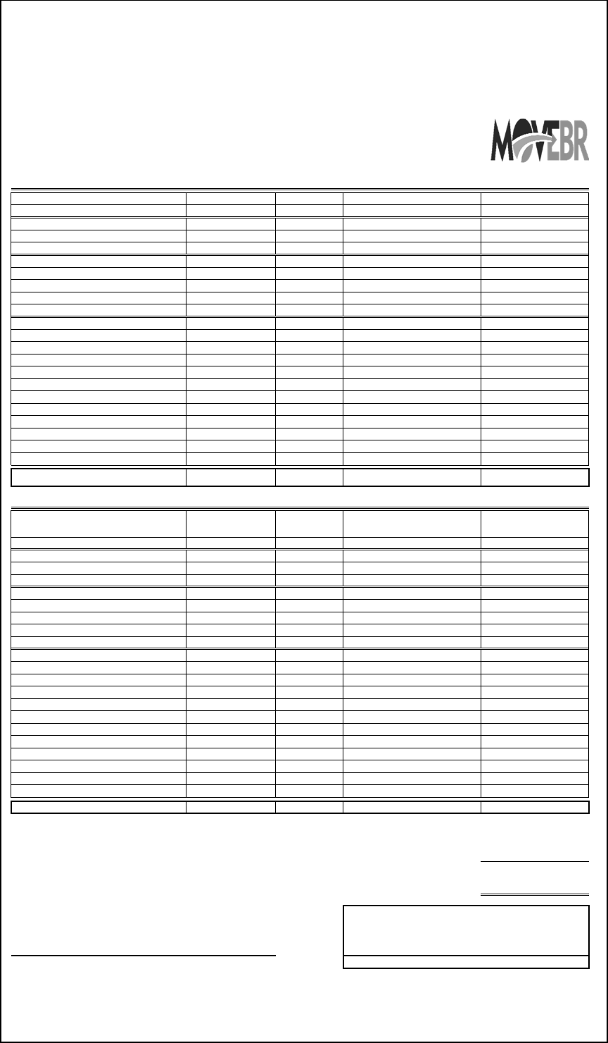
Contract Type: 0 Invoice Number: 0
C.P. Project Number:
0
Date:
1/30/2021
Contract No.:
0
Consultant's Project #:
0
Project Name:
0
Consultant Name:
0 Maximum Lump Sum Limitation =
$ -
Notice to Proceed:
1/0/1900
Period:
2012
Contract Expiration:
1/0/1900
For Professional Engineering Services rendered for the period 12-01-2020 through 12-31-2020
Supplemental Agreement(s) in place:
No
Original Contract:
Task
Fee
% Complete
Amount Earned To Date
Current Period
Preliminary Engineering Services
-
$
-
$
-
$
Corridor Survey -$ -$ -$
Design Study -$ -$ -$
Final Plan Services
-
$
-
$
-
$
Roadway -$ -$ -$
Bridge -$ -$ -$
Sewer -$ -$ -$
Signal Design -$ -$ -$
Other Services
-
$
-
$
-
$
Utility and SUE -$ -$ -$
Full NEPA Services -$ -$ -$
Geotechnical -$ -$ -$
Traffic -$ -$ -$
Landscaping -$ -$ -$
Street Lighting -$ -$ -$
ROW Survey / Mapping -$ -$ -$
Preliminary Plans - SW Project -$ -$ -$
Final Plans - SW Project -$ -$ -$
TBD 3 -$ -$ -$
TBD 4 -$ -$ -$
TBD 5 -$ -$ -$
Total - Original -$ -$ -$
Supplement:
Task Fee % Complete
Amount Earned To Date
Current Period
Preliminary Engineering Services
-
$
-
$
-
$
Corridor Survey -$ -$ -$
Design Study -$ -$ -$
Final Plan Services
-
$
-
$
-
$
Roadway -$ -$ -$
Bridge -$ -$ -$
Sewer -$ -$ -$
Signal Design -$ -$ -$
Other Services
-
$
-
$
-
$
Utility and SUE -$ -$ -$
Full NEPA Services -$ -$ -$
Geotechnical -$ -$ -$
Traffic -$ -$ -$
Landscaping -$ -$ -$
Street Lighting -$ -$ -$
ROW Survey / Mapping -$ -$ -$
Preliminary Plans - SW Project -$ -$ -$
Final Plans - SW Project -$ -$ -$
TBD 3 -$ -$ -$
TBD 4 -$ -$ -$
TBD 5 -$ -$ -$
Supplement Total
-
$
-
$
-
$
-$
-$
-
$
Certified Correct by: Recommend payment of this invoice based on the
monitored work effort and deliverables received.
Project Manager's Signature
MOVEBR Program Management Team
Contact Information Regarding Invoicing Questions:
Name:
0
Phone:
0
Email:
0
Total Invoiced to Date (Combined)
Less Previously Invoiced to Date (Combined)
Total Amount Due This Invoice
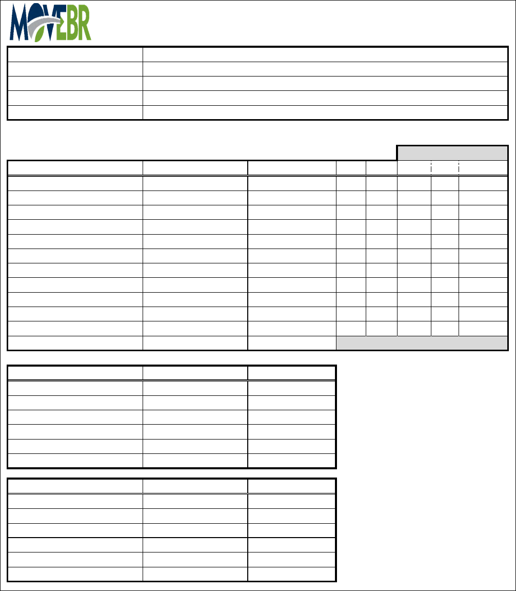
Company:
Contract Number:
Project Number:
Project Name:
Invoice Period:
Table 1
Company Invoiced This Period Invoiced To Date Local State MBE WBE VBE
0
-
$
-
$
0
0
0
0
0
0
-
$
-
$
0
0
0
0
0
0
-
$
-
$
0
0
0
0
0
0
-
$
-
$
0
0
0
0
0
0
-
$
-
$
0
0
0
0
0
0
-
$
-
$
0
0
0
0
0
0
-
$
-
$
0
0
0
0
0
0
-
$
-
$
0
0
0
0
0
0
-
$
-
$
0
0
0
0
0
0
-
$
-
$
0
0
0
0
0
0
-
$
-
$
0
0
0
0
0
TOTAL
-
$
-
$
Table 2
Category in Dollars Invoiced This Period Invoiced To Date
LOCAL DOLLARS
-
$
-
$
STATE DOLLARS
-
$
-
$
MBE/WBE/VBE DOLLARS
-
$
-
$
MBE DOLLARS
-
$
-
$
WBE DOLLARS
-
$
-
$
VBE DOLLARS
-
$
-
$
Table 3
Category in Percentage Invoiced This Period Invoiced To Date
LOCAL DOLLARS
0%
0%
STATE DOLLARS
0%
0%
MBE/WBE/VBE DOLLARS
0%
0%
MBE DOLLARS
0%
0%
WBE DOLLARS
0%
0%
VBE DOLLARS
0%
0%
Form Version 1/27/2020
<--Classification dollars are for companies that meet
at least one of the categories (MBE, WBE, VBE).
<--Classification % are for companies that meet at
least one of the categories (MBE, WBE, VBE).
Type X to note applicable classification(s).
Classification
Contract Activity Reporting
0
0
0
:
12-01-2020 through 12-31-2020

Definitions
Invoiced Totals Need to Match the Correct Category Chosen for the Companies Identified Above.
Excel Spreadsheet will automatically calculate total based on if "X" is noted in Table 1
"Invoiced to Date" is to included "Invoiced this Period" dollars.
State - means a business that has a permanent address within the State of Louisiana for a period of at least12 months. Temporary
construction offices or Post office boxes do not constitute a business location under this definition
Notes
“Minority Business Enterprise” (MBE) – means a business which is at least fifty-one percent (51%) owned by African Americans,
American Indians, Asians, Filipinos, and/or Latinos and whose management and daily operation is controlled by one or more members
of the identified ethnic groups.
“Women Business Enterprise” (WBE) – means a business which is at least fifty-one percent (51%) owned by one or more women and
whose management and daily operation is controlled by the qualifying parties .
“Veteran Business Enterprise” (VBE) – means a business which is at least fifty-one percent (51%) owned by one or more Veterans
and whose management and daily operation is controlled by the qualifying parties.
Local – means a business that has a permanent address within the Parish of East Baton Rouge for a period of at least 12 months prior
to the date of this contract. Temporary construction offices or Post office boxes do not constitute a business location under this
definition
Date:
1
6
2
7
3
8
4
9
5
10
Project Name: 0
Progress Report
Company Name: 0
City-Parish Project No.: 0
For Period:
12-01-2020 through 12-31-2020
Work Completed:
Work in Progress:
Problems/Concerns:
Upcoming Submittals:
Action Items:
Other:
Schedule (See Attached)

CONSULTANT SERVICES MANUAL
57 MOVEBR CONSULTANT SERVICES MANUAL / MAR. 2021
Attachment E
Sample Project Schedule
ID Task
Mode
Task Name
1
MOVEBR SAMPLE PROJECT SCHEDULE
2
PRELIMINARY ENGINEERING
3
DTD Issues NTP #1
4
Kick off Meeting
5
CORRIDOR SURVEY
6
Establish Control Traverse
7
Submit Control Traverse
8
Review Control Traverse
9
Address Control Traverse Comments
10
Review Revised Control Traverse
11
Corridor Survey
12
Submit Corridor Survey
13
Review Corridor Survey
14
Address Corridor Survey Comments
15
Review Corridor Survey Comments
16
Finalize Corridor Survey
17
Submit Final Corridor Survey
18
TRAFFIC DESIGN STUDY
19
Prepare Traffic Methodology
20
Review Traffic Methodology
21
Prepare Traffic Design Report
22
Review Traffic Report
23
Revise Traffic Report
24
Review Revised Traffic Report
25
Finalize Traffic Report
26
DESIGN STUDY
27
Prepare Design Study
28
Submit Design Study
29
Review Design Study
30
MPC Approves Project Contracting Approach
31
MTC Approves Going to Final Design
32
Public Meeting (Final Design Study)
33
Send Design Study Review Comments to Consultant
34
Address Design Study Review Comments
35
Submit Final Design Study
36
Review Final Design Study
37
FINAL DESIGN
38
Issues Notice to Proceed Final Design
39
30% Design (Geometry & Cross Sections )
40
Submit 30% Design
41
30% Design Review
42
30% Design Send Comments to Consultant
43
Hydraulic Design
44
Hydraulic Submittal
45
Hydraulic Review
46
Send Hydraulic Review Comments to Consultant
47
Consultant prepares Responses to Hydraulic Review Comments
48
MOVEBR Reviews Responses
49
Consultant Resubmits Hydraulic Review for Approval
50
MOVEBR Accepts Final Submittal
51
Consultant Prepares Utility Space Allocation
52
Prepare Plan in Hand Prints W/SOC
Jan
Feb
Mar
Apr
May
Jun Jul
Aug
Sep Oct
Nov
Dec Jan FebMarApr
May
Jun Jul
Aug
Sep Oct
Nov
Dec
Jan
1st Quarter
2nd Quarter
3rd Quarter
4th Quarter
1st Quarter
2nd Quarter
3rd Quarter
4th Quarter
1st Quarter
Task
Split
Milestone
Summary
Project Summary
Inactive Task
Inactive Milestone
Inactive Summary
Manual Task
Duration-only
Manual Summary Rollup
Manual Summary
Start-only
Finish-only
External Tasks
External Milestone
Deadline
Progress
Manual Progress
Page 1
Project: Sample_Project_Schedu
Date: Thu 2/11/21
ID Task
Mode
Task Name
53
Submit Plan in Hand Prints w/ SOC
54
MOVEBR Distributes PIH Prints w/ Transmittal Letter
55
Plan in Hand Constructability Review
56
Plan in Hand Meeting and Field Review
57
Send PIH Review Comments to Consultant
58
Consultant Prepares PIH Responses
59
Consultant Submits PIH Responses to PMT
60
PMT Reviews PIH Responses
61
PMT Approves PIH Responses
62
Prepare 90% ACPs
63
Submit 90% ACPs
64
Review 90% ACPs
65
MTC Authorizes Final Design
66
Send 90% ACP Comments
67
Consultant Prepares 90% Responses
68
Consultant Submits 90% Responses to PMT
69
PMT Reviews 90% Responses
70
PMT Approves 90% Responses
71
Prepare 100% Final Plans
72
Submit 100% Final Plans
73
MOVEBR Accepts 100% Final Plans
74
MTC Authorize Advertise for Bid
75
Final Plans Complete
76
ROW MAPS & DOCS
77
Provide Deed Abstracts to Consultant
78
ROW Survey and Existing Property Line Map
79
MOVEBR Final Taking Meeting
80
Provide Full Abstracts to Consultant
81
Base Right of Way Maps
82
Submit Base Right of Way Maps
83
Review Base Right of Way Maps
84
Base ROW Map Comments Sent to Consultant
85
Address ROW Comments
86
Submit Revised Base Right of Way Map
87
Prepare Right of Way Acquisition Set
88
MOVEBR Reviews Acquisition Set
89
Address Acquisition Set Comments
90
Submit Final ROW Acquisition Set
91
Prepare Right-of-Way Recordation Set
92
Review Right-of-Way Recordation Set
93
Resubmit Right-of-Way Recordation Set
94
Submit Right-of-Way Recordation Set
95
CLEARING & GRUBBING DESIGN
96
Prepare Clearing and Grubbing Plans
97
Submit Clearing and Grubbing Plans
98
Review Clearing and Grubbing Plans
99
Send comments to Consultant Clearing and Grubbing
100
Address Review Comments (Clearing and Grubbing)
101
MOVEBR Accepts Responses to Comments (Clearing and Grubbing)
102
Revise Clearing and Grubbing Plans (Clearing and Grubbing)
103
Submit Final Clearing and Grubbing Plans
104
PM Accepts Clearing and Grubbing Plans
Jan
Feb
Mar
Apr
May
Jun Jul
Aug
Sep Oct
Nov
Dec Jan FebMarApr
May
Jun Jul
Aug
Sep Oct
Nov
Dec
Jan
1st Quarter
2nd Quarter
3rd Quarter
4th Quarter
1st Quarter
2nd Quarter
3rd Quarter
4th Quarter
1st Quarter
Task
Split
Milestone
Summary
Project Summary
Inactive Task
Inactive Milestone
Inactive Summary
Manual Task
Duration-only
Manual Summary Rollup
Manual Summary
Start-only
Finish-only
External Tasks
External Milestone
Deadline
Progress
Manual Progress
Page 2
Project: Sample_Project_Schedu
Date: Thu 2/11/21
